Multicore Programming of a Field-Oriented Control on Zynq
This example demonstrates how to implement a control algorithm that contains multiple rates on Zynq®. To take advantage of both the cores and the FPGA hardware, the example uses a graphical partitioning approach such that code from different partitions is distributed across the cores and the hardware.
Introduction
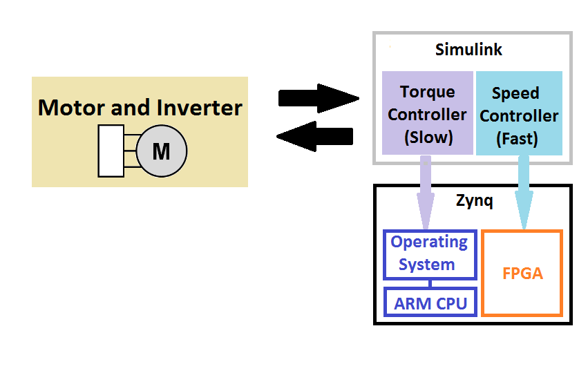
This example shows a workflow for generating code for a motor control algorithm and testing the generated code on a Xilinx® Zynq-7000 SoC ZC702 evaluation board. The motor control algorithm in the example is a Field-Oriented Control algorithm composed of a speed controller (fast component) and a torque controller (slow component). One typical workflow is to generate code for these two components of the controller, upload the generated code to an evaluation board, and then connect the evaluation board to a real-world motor. The block diagram illustrates this workflow.
So that the example is self-contained and because the target processor has redundant computer power, this example models the motor using one of the tasks of the CPU of the evaluation board.
The example assumes that a Xilinx Zynq-7000 SoC ZC702 evaluation board is connected to your computer. For information about connection and installation, see Install Support for AMD SoC Boards (Embedded Coder).
This example requires Embedded Coder® to generate multi-threaded code, HDL Coder™ to generate HDL code, and Simscape™ Power Systems™ to model the permanent magnet synchronous machine in the example. You cannot generate HDL code on Macintosh systems.
Example Model
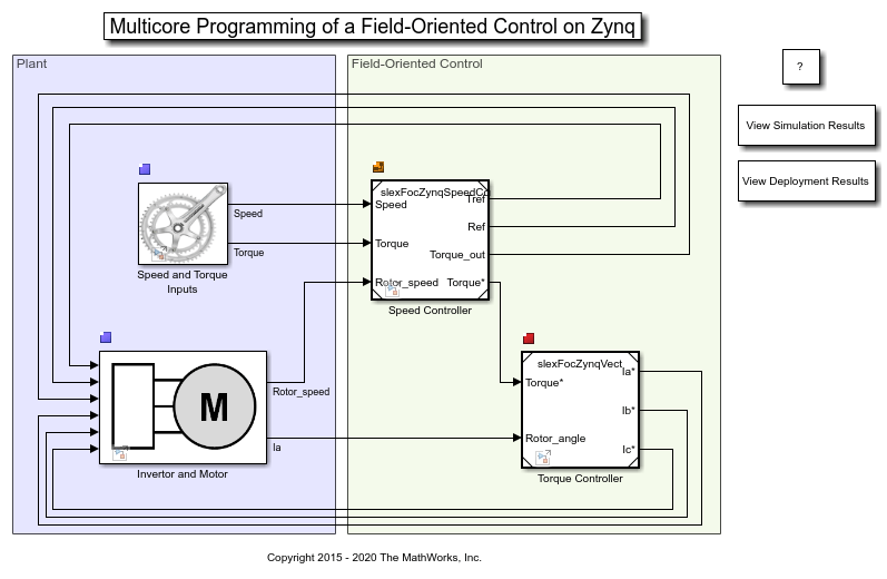
The example model consists of two Simulink® areas. In the Permanent Magnet Synchronous Machine area, there are two blocks: "Speed and Torque Inputs" block which provides the reference inputs to the feedback system, and "Invertor and Motor" block which is the plant we aim to control in this example. The "Invertor and Motor" block also contains peripherals: a scope that can be used for investigating the simulation results and a UDP sender. The generated code for the UDP sender is responsible for sending the simulation data from the Zynq ZC702 evaluation board to the host machine. The Field-Oriented Control contains the controller blocks "Speed controller" and "Torque controller". To load the model, enter
slexFocZynqExample
Architecture Definition
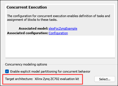
The target architecture in the example is Xilinx Zynq ZC702 evaluation kit. This can be verified by accessing the Concurrent Execution dialog box.
In the Modeling tab, select Model Settings. In the Model Configuration Parameters dialog box, on the Solver tab, select Allow tasks to execute concurrently on target, then click Configure Tasks.
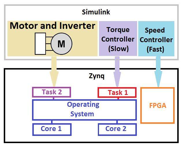
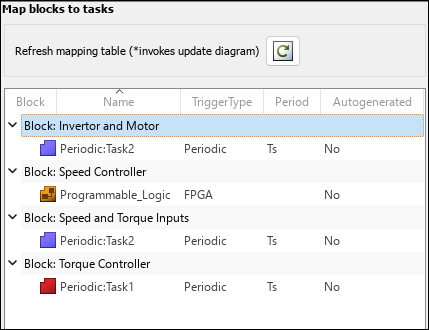
The evaluation board has an ARM® Cortex®-A9 CPU and a field-programmable gate array (FPGA). There are two tasks running on the ARM CPU. The "Torque controller" is mapped to the first task and the blocks that constitute the plant ("Speed and Torque Inputs" block and "Invertor and Motor") are mapped to the second task. The "Speed controller", which operates at high frequency in the control loop, is mapped to the FPGA. These settings can be changed in the "Tasks and Mapping" section of the "Concurrent Execution" dialog box.
Generate Multi-Threaded and HDL Code
Enter Ctrl-B or select Deploy to Hardware to generate the multi-threaded and HDL code. The generated executable and the FPGA bitstream will be uploaded to Zynq board automatically. This step requires that the Zynq board is connected to the computer and that the environment is set up properly. For more information, see Install Support for AMD SoC Boards (Embedded Coder).
Receive Data from the Zynq
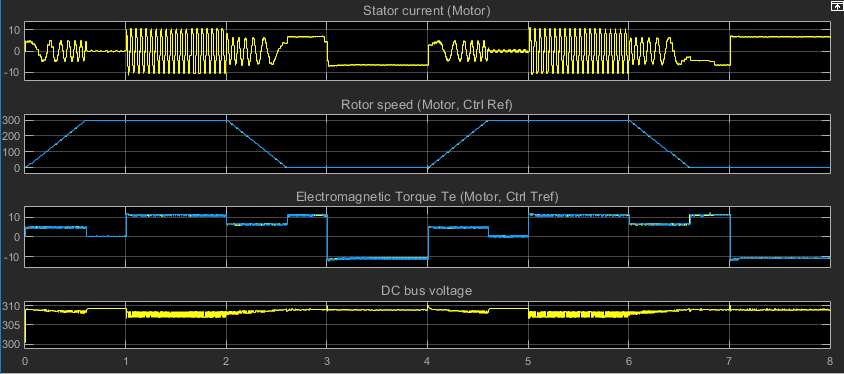
Open the scope by selecting View Simulation Results, and run the simulation to obtain the following output:
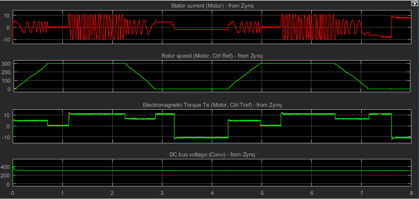
Compare this simulation output with the output of the executable that runs on the Zynq ZC702 board. In order to make this comparison, access the UDP receiver model by selecting View Deployment Results. When the UDP receiver model is selected, run the simulation. The run command will send a signal to the Zynq ZC702 board to start running the executable on the board. The simulation data will be sent via UDP from the Zynq ZC702 board to the host machine. The captured UDP signal is displayed on the scope of the UDP Receiver model.
Close the Model
close_system('slexFocZynqExample', 0);