Composite Interface Guidelines
To simplify model appearance, you can group signals, messages, or conserving connections to create composite interfaces for model components and blocks. Composite interfaces reduce the number of ports on a model component and the number of lines in a block diagram. Elements of a composite interface retain their separate identities.
Virtual buses meet most modeling requirements for composite interfaces, and they give you the flexibility to group different types of elements. They reduce line complexity and clutter in a block diagram and make it easier to change the interface incrementally. For example, if you must add or remove elements from a component interface, modifying a bus can be simpler than adding or removing ports.
When you create a composite interface, such as a virtual bus, group lines based on their functionality. By organizing signals, messages, or connections into logical groupings, you reduce the likelihood of significant refactoring in the future.
At component interfaces, use In Bus Element and Out Bus Element blocks. In Bus Element blocks let you extract bus elements by name at their point of use. Out Bus Element blocks let you build an output bus by connecting elements to multiple Out Bus Element blocks for the same output port.
To enforce the composition of a bus at an interface, use a Simulink.Bus object.
To implement the bus definition as a structure in generated code or to iteratively process buses in a subsystem such as a for-each subsystem, consider making the virtual buses into nonvirtual buses.
Visualize Composite Interfaces
Suppose you have this relatively simple model.
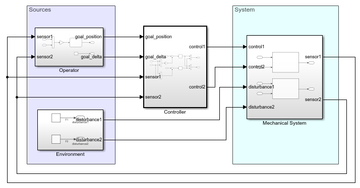
Each component interface in this model has multiple ports, and the signal lines clutter the model.
With composite interfaces, you can simplify the block diagram by reducing the number of lines.

Virtual buses simplify the signal lines in the block diagram based on four different types of functionality: sensor data, system goals, control signals, and system disturbances.
The components use In Bus Element and Out
Bus Element blocks at their interface. For example, consider the contents of the
subsystem named Controller.
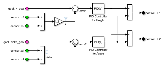
Each In Bus Element and Out Bus Element block has a label
that displays the corresponding element, for example, sensor.x1. In this
example, sensor is the name of the port, and x1 is the
name of the bus element. Two In Bus Element blocks select this element to
avoid a branched signal line.
Define Composite Interfaces
Before you create composite interfaces, consider your high-level and low-level modeling requirements.
Decide how to group signals, messages, or conserving connections based on your high-level modeling requirements. | |
Compare virtual buses, nonvirtual buses, and arrays of buses against low-level modeling requirements. |
Tip
To identify the boundaries, scope of data, and interface attributes of your model component, see Define Interfaces and Manage Data of Simulink Components.