Model and Simulate Services of Brake Control System
R2026bThis example shows how to simulate and validate a brake control system software architecture using the Software Component Designer app. You simulate the architecture with a mock run-time environment (RTE), then inspect logged signals to validate queued send-receive and client-server communication patterns.
Open the Software Architecture
Open the software architecture model. The architecture contains four components:
Sensor – Measures distance to the object ahead and sends the data value to a queue.
Controller – Processes distance values, checks whether the vehicle needs to start braking, and sends a braking command value to a queue.
Actuator – Processes brake commands. When new data arrives, the actuator triggers the braking action and requests the velocity of the vehicle.
Speedometer – Provides the current velocity of the vehicle.
model = systemcomposer.openModel('SWArch');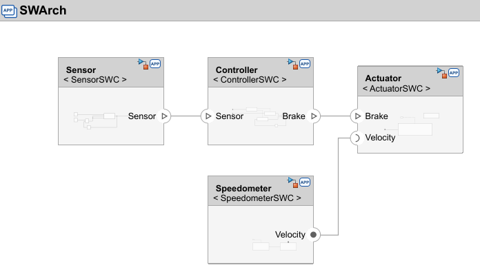
The sensor, controller, and speedometer components each have a periodic component function. To view these component functions, their execution order, and sample times, open the Functions Editor (System Composer). From the toolstrip, on the Modeling tab, click Functions Editor.
When you open the Functions Editor, the model automatically updates and the table displays the component functions in order of execution:
Order | Function | Component | Sample Time (s) | Description |
|---|---|---|---|---|
1 |
| Speedometer |
| Updates the velocity value |
2 |
| Sensor |
| Updates the distance value |
3 |
| Controller |
| Reads distance, updates brake command |
Each component logs signals and sends data to the Simulation Data Inspector.
Simulate the Brake Control System
Simulate the software architecture with a mock RTE. The mock RTE emulates application communication through middleware and validates component behaviors configured by quality of service (QoS) properties, such as queued communication, execution on data arrival, and function calls.
out = sim('SWArch');Validate Queued Send-Receive Communication
The sensor component sends distance values to a queue and the controller component reads values from that queue. Plot the sensorDistanceSent and controllerDistanceReceived signals to compare the queued communication behavior.
plotSWCDesignerSignals("queued");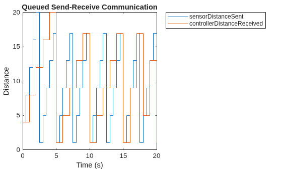
The sensorDistanceSent signal starts at 4 and updates every 0.5 seconds. The controllerDistanceReceived signal starts at 4 and updates every 1 second.
Within the first second of simulation, the mock RTE executes these tasks in order:
At s, the sensor pushes a value of
4into the queue.At s, the sensor pushes a value of
8into the queue.At s, the controller receives the queued values, pops and reads the oldest value from the queue,
4.
The mock RTE maintains a receiver queue with one value, 8. The sensor pushes values twice as fast as the controller reads them, so the queue eventually fills to its capacity of 16.
Inspect the controllerDistanceReceived signal at s to see the queue overflow. Between controller reads, the sensor pushes two values (5 at s and 9 at s), but the queue can only keep one new value by dropping the oldest. The controller reads 9 and drops 5.
Display the sensor and controller values around the queue overflow point to confirm the data loss.
displayQueueOverflow
ans = 5×2 timetable
      Time      sensorDistanceSent    controllerDistanceReceived
    ________    __________________    __________________________

    15 sec               1                         1
    15.5 sec             5                       NaN
    16 sec               9                         9
    16.5 sec            13                       NaN
    17 sec              17                        17
The sensor sends 1, 5, and 9 between s and s, but the controller only reads 1 and 9, confirming that 5 was dropped when the queue overflowed.
Validate Client-Server Communication
The actuator component requests vehicle speed and the speedometer component provides the current vehicle speed. Plot the speedometerGeneratedVelocity and actuatorCurrentVelocity signals to verify the actuator receives the correct velocity at each request.
plotSWCDesignerSignals("client-server");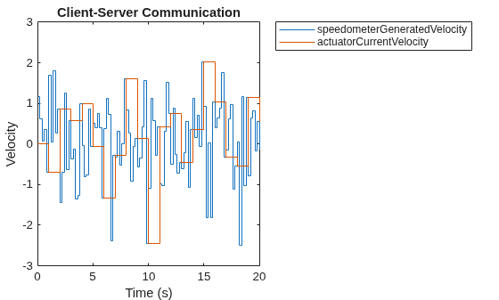
The speedometer randomly generates the speedometerGeneratedVelocity signal, which updates every 0.2 seconds. The actuatorCurrentVelocity signal updates every 1 second. At each actuator execution, the velocity value matches the speedometer value from the previous speedometer execution (0.2 seconds earlier). For example, at s, the actuator receives the velocity that the speedometer generated at s.
This one-step lag is expected behavior for the mock RTE. The generate_velocity function and the getCurrentVelocity server both execute within the same time step, but the server reads the velocity value that was stored before the current step began. The logged speedometerGeneratedVelocity signal reflects the newly computed value, while the actuator receives the previously stored value through the client-server call.
Inspect Component QoS Configurations
From the software architecture, you can view and edit the quality of service (QoS) properties of each component. To inspect the QoS configuration of a component:
Select a component port on the canvas.
Open the Property Inspector and select the Parameters tab.
Select a data element or function element.
View properties on the Service tab.
You can also view the linked Simulink software component model by double-clicking the component. The following sections show the QoS configuration for each component and relate it to the simulation results.
Sensor Output: Queued Sender Configuration
From the logged sensorDistanceSent signal, the sensor sends a new distance value to a queue every 0.5 seconds. Select the output port named Sensor, then select the Distance element. The Service tab shows:
Sender service –
Default: QueuedSample time – -1 (inherited)
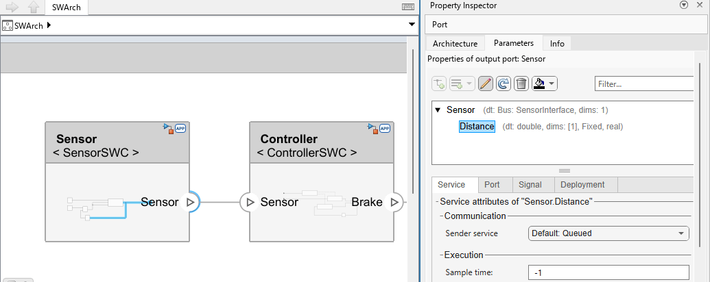
The sensor has a component function, measure_distance, with a sample time of 0.5. Open the sensor component to view the implementation.
open_system('SensorSWC');The component function measure_distance runs every 0.5 seconds. The counter increments distance by 4, starting at 4, and resetting to 1 when the value exceeds 20.
Controller Input: Queue Capacity and Overflow
From the logged controllerDistanceReceived signal, the controller receives two new distance values in the queue every second. Based on the change in behavior at s, the queue size is 16.
Select the input port named Sensor, then select the Distance element. The Service tab shows:
Receiver service –
Default: QueuedQueue capacity (instance value) –
Inherited: 16Initial value –
0Status element –
Distance_statusTimeout (instance value) –
Inherited: InfSample time (s) –
-1(inherited)
Select the output port named Brake, then select the BrakeCmd element. Sender service is Queued.
The controller has a component function, check_safety_conditions, with a sample time of 1. Open the controller component to view the implementation.
open_system('ControllerSWC');The controller checks safety conditions using a conditional algorithm that compares the Distance value with an upper bounded threshold of 13. When the Distance value is below the threshold, the controller updates the BrakeCmd value to true.
Actuator: Data-Triggered Execution and Client Requests
From the logged actuatorCurrentVelocity signal, the actuator requests the current velocity every 1 second. The controller sends a new BrakeCmd data value to a queue every 1 second, which means the actuator also executes every 1 second. When a new BrakeCmd data value arrives, the actuator executes and requests the current velocity.
Select the input port named Brake, then select the BrakeCmd element. The Service tab shows:
Receiver service –
Default: QueuedQueue capacity (instance value) –
Inherited: 16Initial value –
0Status element –
<None>Timeout (instance value) –
Inherited: InfOn data arrival, execute –
OnBrakeCommand
Select the client port named Velocity, then select the velocity = getCurrentVelocity() element. The Service tab shows:
Timeout (instance value) –
Inherited: Inf(timeout monitoring disabled)Caller behavior –
Wait for server results(actuator only accepts server results available in the same time step)
Open the actuator component to view the implementation.
open_system('ActuatorSWC');The Function-Call Subsystem block in the actuator uses data-triggered execution. The Inport block named OnBrakeCommand produces a function call when the actuator receives new BrakeCmd data values. The actuator executes the braking action, which checks for a positive velocity value.
Speedometer: Server Function Mapping
From the logged speedometerGeneratedVelocity signal, the speedometer updates the velocity every 0.2 seconds. The actuator requests the current velocity from the speedometer every 1 second.
Select the server port named Velocity, then select the velocity = getCurrentVelocity() element. On the Service tab, Simulink function is getCurrentVelocity, mapping the server port to the Simulink Function block.
Open the speedometer component to view the implementation.
open_system('SpeedometerSWC');The Function-Call Subsystem block in the speedometer executes every 0.2 seconds, which is specified in the Inport block named Task_200ms. The speedometer generates velocity values using a random number generator algorithm, which provides the velocity value to the getCurrentVelocity Simulink Function block.
Summary
In this example, you simulate a brake control system software architecture and validate two communication patterns:
Queued send-receive – The sensor sends distance values faster than the controller reads them. When the queue fills to capacity, the oldest values are dropped, confirming the QoS queue capacity setting of
16.Client-server – The actuator requests velocity from the speedometer on each execution. The one-step lag between generated and received values confirms expected mock RTE behavior.
To experiment further, try adjusting the queue capacity or sample times on the component ports and re-running the simulation to observe the effects on data loss and timing.
Clean Up
Close the models opened by this example and clear the Simulation Data Inspector.
cleanupSWCDesignerExample;

