Margins Goal
Purpose
Enforce specified gain and phase margins when using Control System Tuner.
Description
Margins Goal uses the notion of disk margin to enforce specified gain and phase margins on SISO or MIMO feedback loops. Disk margins provide a more complete picture of robust stability as they take into account all frequency and loop interactions. Therefore, disk-based margins provide a stronger guarantee of stability than the classical gain and phase margins.
For SISO feedback loops, the disk-based gain and phase margins are typically smaller but similar to the classical gain and phase margins.
For MIMO feedback loops, the disk-based margins account for loop interactions and can be much smaller than classical loop-at-a-time gain and phase margins. The disk-based margins guarantee stability against gain or phase variations across all feedback channels. The gain or phase can change in all channels simultaneously, and by a different amount in each channel.
For information about disk margins, see Stability Analysis Using Disk Margins (Robust Control Toolbox).
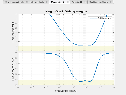
In Control System Tuner, the shaded area on the plot represents the region in the frequency domain where the margins goal is not met. For more information about interpreting this plot, see Stability Margins in Control System Tuning.
Creation
In the Tuning tab of Control System Tuner, select New Goal > Minimum stability margins to create a Margins Goal.
Command-Line Equivalent
When tuning control systems at the command line, use TuningGoal.Margins to specify a stability margin goal.
Feedback Loop Selection
Use this section of the dialog box to specify the signal locations at which to measure stability margins. You can also specify additional loop-opening locations for evaluating the tuning goal.
Measure stability margins at the following locations
Select one or more signal locations in your model at which to compute and constrain the stability margins. To constrain a SISO loop, select a single-valued location. For example, to constrain the stability margins at a location named
'y', click Add signal to list and select
 'y'. To constrain a MIMO loop, select multiple signals or a vector-valued signal.Measure stability margins with the following loops open
Select one or more signal locations in your model at which to open a feedback loop for the purpose of evaluating this tuning goal. The tuning goal is evaluated against the open-loop configuration created by opening feedback loops at the locations you identify. For example, to evaluate the tuning goal with an opening at a location named
'x', click
Add signal to list and select 'x'.
Tip
To highlight any selected signal in the Simulink® model, click ![]() . To remove a signal from the input or output list, click
. To remove a signal from the input or output list, click ![]() . When you have selected multiple signals, you can reorder
them using
. When you have selected multiple signals, you can reorder
them using ![]() and
and ![]() . For more information on how to specify signal locations
for a tuning goal, see
Specify Goals for Interactive Tuning.
. For more information on how to specify signal locations
for a tuning goal, see
Specify Goals for Interactive Tuning.
Desired Margins
Use this section of the dialog box to specify the minimum gain and phase margins for the feedback loop.
Gain margin (dB)
Enter the required minimum gain margin for the feedback loop, specified as a scalar value in dB. The tuning goal uses disk-based gain and phase margins, which provide a stronger guarantee of stability than the classical gain and phase margins. (For details about disk margins, see Stability Analysis Using Disk Margins (Robust Control Toolbox).)
The gain margin indicates how much the gain of the open-loop response can increase or decrease without loss of stability. For instance,
For a SISO system, entering
3specifies a requirement that the closed-loop system remain stable for changes in the open-loop gain of up to ±3 dB.For a MIMO system, entering
3specifies a requirement that the closed-system remain stable for gain changes up to ±3 dB in each feedback channel. The gain can change in all channels simultaneously, and by a different amount in each channel.
Phase margin (degrees)
Required minimum phase margin for the feedback loop, specified as a scalar value in degrees. The tuning goal uses disk-based gain and phase margins, which provide a stronger guarantee of stability than the classical gain and phase margins. (For details about disk margins, see Stability Analysis Using Disk Margins (Robust Control Toolbox).)
The phase margin indicates how much the phase of the open-loop response can increase or decrease without loss of stability. For instance,
For a SISO system, entering
45specifies a requirement that the closed-loop system remain stable for changes of up to ±45° in the phase of the open-loop response.For a MIMO system, entering
45specifies a requirement that the closed-system remain stable for phase changes up to ±45° in each feedback channel. The phase can change in all channels simultaneously, and by a different amount in each channel.
Options
Use this section of the dialog box to specify additional characteristics of the stability margin goal.
Enforce goal in frequency range
Limit the enforcement of the tuning goal to a particular frequency band. Specify the frequency band as a row vector of the form
[min,max], expressed in frequency units of your model. For example, to create a tuning goal that applies only between 1 and 100 rad/s, enter[1,100]. By default, the tuning goal applies at all frequencies for continuous time, and up to the Nyquist frequency for discrete time.For best results with stability margin requirements, pick a frequency band extending about one decade on each side of the gain crossover frequencies.
D scaling order
This value controls the order (number of states) of the scalings involved in computing MIMO stability margins. Static scalings (scaling order 0) are used by default. Increasing the order may improve results at the expense of increased computations. If the stability margin plot shows a large gap between the optimized and actual margins, consider increasing the scaling order. See Stability Margins in Control System Tuning.
Apply goal to
Use this option when tuning multiple models at once, such as an array of models obtained by linearizing a Simulink model at different operating points or block-parameter values. By default, active tuning goals are enforced for all models. To enforce a tuning requirement for a subset of models in an array, select Only Models. Then, enter the array indices of the models for which the goal is enforced. For example, suppose you want to apply the tuning goal to the second, third, and fourth models in a model array. To restrict enforcement of the requirement, enter
2:4in the Only Models text box.For more information about tuning for multiple models, see Robust Tuning Approaches (Robust Control Toolbox).
Algorithms
When you tune a control system, the software converts each tuning goal into a normalized scalar value f(x). Here, x is the vector of free (tunable) parameters in the control system. The software then adjusts the parameter values to minimize f(x) or to drive f(x) below 1 if the tuning goal is a hard constraint.
For Margins Goal, f(x) is given by:
S = D–1[I – L(s,x)]–1D is the scaled sensitivity function.
L(s,x) is the open-loop response being shaped.
D is an automatically-computed loop scaling factor. For more information about D, see Stability Margins in Control System Tuning.
α is a scalar parameter computed from the specified gain and phase margin. For more information about α, see Stability Analysis Using Disk Margins (Robust Control Toolbox).
This tuning goal imposes an implicit stability constraint on the closed-loop sensitivity function measured at the specified, evaluated with loops opened at the specified loop-opening locations. The dynamics affected by this implicit constraint are the stabilized dynamics for this tuning goal. The Minimum decay rate and Maximum natural frequency tuning options control the lower and upper bounds on these implicitly constrained dynamics. If the optimization fails to meet the default bounds, or if the default bounds conflict with other requirements, on the Tuning tab, use Tuning Options to change the defaults.