Specify Portion of Model to Linearize in Simulink Model
To specify the portion of the model to linearize, you can define and save linear analysis points directly in your Simulink® model. Analysis points represent linearization inputs, outputs, and loop openings for your model.
Alternatively, to specify analysis points without changing your model, you can define analysis points:
In the Model Linearizer. For more information, see Specify Portion of Model to Linearize in Model Linearizer.
At the command line. For more information, see Specify Portion of Model to Linearize at Command Line.
Specify Analysis Points
To specify analysis points directly in your Simulink model, first open the Linearization tab. To do so, in the Apps gallery, click Linearization Manager.
To specify an analysis point:
In the model, click the signal you want to define as an analysis point.
On the Linearization tab, in the Insert Analysis Points gallery, select the type of analysis point you want to define.
 Input Perturbation — Specifies an additive input to a
signal.
Input Perturbation — Specifies an additive input to a
signal. Output Measurement — Takes a measurement at a
signal.
Output Measurement — Takes a measurement at a
signal. Loop Break — Specifies a loop opening.
 Open-Loop Input — Specifies a loop break followed by an
input perturbation.
Open-Loop Input — Specifies a loop break followed by an
input perturbation. Open-Loop Output — Specifies an output measurement
followed by a loop break.
Open-Loop Output — Specifies an output measurement
followed by a loop break. Loop Transfer — Specifies an output measurement before a
loop break followed by an input perturbation.
Loop Transfer — Specifies an output measurement before a
loop break followed by an input perturbation. Sensitivity — Specifies an input perturbation followed by
an output measurement.
Sensitivity — Specifies an input perturbation followed by
an output measurement. Complementary Sensitivity — Specifies an output
measurement followed by an input perturbation.
Complementary Sensitivity — Specifies an output
measurement followed by an input perturbation.
Alternatively, you can right-click the signal and, in the Linearization manager app section
 , select a type of analysis point.
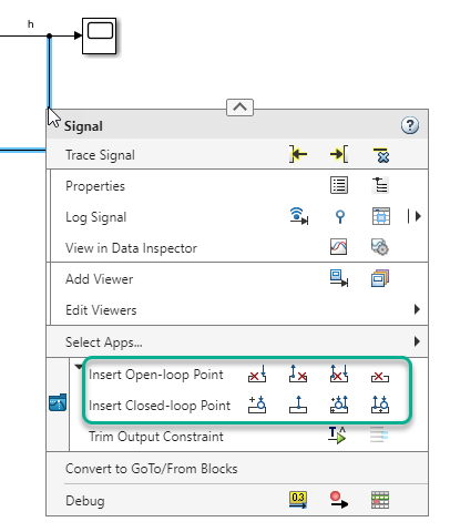
For more information on the different types of analysis points, see Specify Portion of Model to Linearize.
When you specify analysis points, the software adds annotations to your model indicating the linear analysis point type.
Repeat steps 1 and 2 for all signals you want to define as analysis points.
For each linear analysis point that you specify, the software adds an annotation to your model indicating the analysis point type.
Select Bus Elements as Analysis Points
This example shows how to select individual elements in a bus signal as analysis points.
Open Simulink model.
sys = 'scdbusselection';
openExample(sys)
Specify a bus signal as a linear analysis point.
First, open the Linearization tab. In the Simulink model window, in the Apps gallery, click Linearization Manager.
In the model, click a bus signal, such as the
OUTPUTBUSsignal. On the Linearization tab, click Select Bus Element.
In the Select Linearization Points in the Bus dialog box, in the Signals in the Bus section, expand the
limitsbus, and selectupper_saturation_limit.limitsis a nested bus within theOUTPUTBUSsignal.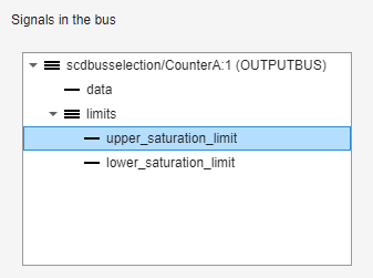
To add the selected signal to the Analysis I/Os section, click Add. By default, the signal is configured as an
Input Perturbationanalysis point.
You can change the analysis point type using the Configuration drop-down list. For example, to specify a linearization output point, select
Output Measurement.
To add additional analysis points from within the same bus signal, repeat step 2.
To remove an analysis point, select the signal in the Linearization Inputs/Outputs section, and click Delete.
Once you have defined all of the required analysis points for that bus, click OK.
To specify analysis points for another bus signal, repeat steps 2 and 3.
To view linear analysis point indicators in the Simulink model, on the Linearization tab, in the Insert Analysis Points gallery, select Linearization Indicators.
The software adds graphical annotations to the bus signals indicating the type of analysis points specified. For example, if you specify a linearization input in the
COUNTERBUSsignal and a linearization output in theOUTPUTBUSsignal, the software adds the corresponding annotations to the signals.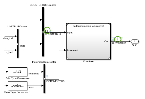
You can specify different analysis point types for multiple elements in the same bus. In this case, the software adds the
 annotation to the signal.