Create and Update Instrument Panel for Stateflow Car Transmission
This example shows how to generate an App Designer instrument panel for a Simulink® Real-Time™ model, then update the instrument panel by adding controls for more signals. Use this example to follow the iterative process of developing an instrument panel by using the Simulink Real-Time App Generator and App Designer.
Create Target Object and Connect
Create a Target object for the default target computer and connect to the target computer. In the Command Window, type:
tg = slrealtime;
connect(tg);
Build and Load the Real-Time Application
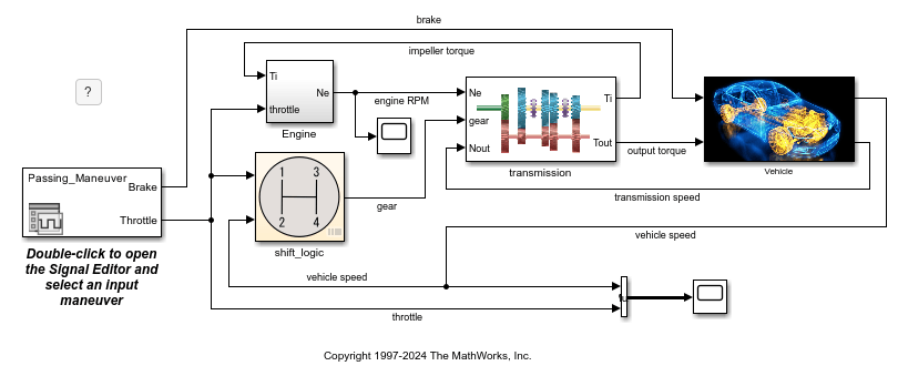
Open the slrt_ex_sf_car model and load the external data for the model. Build and load the real-time application.
model = 'slrt_ex_sf_car';
open_system(model);
modelSTF = getSTFName(tg);
set_param(model,"SystemTargetFile",modelSTF);
evalc('slbuild(model)');
load(tg,model);
This example loads the real-time application on the target computer. But, you do not have to have a real-time application loaded on the target computer to use the Simulink Real-Time App Generator to generate an instrument panel app.
Open Simulink Real-Time App Generator and Configure Controls
As described in Simulink Real-Time App Generator, you can start creating an App Designer instrument panel from the real-time application MLDATX file.
Open the Simulink Real-Time App Generator by using the command
slrtAppGeneratorin the Command Window.Select New > New. Then, select the real-time application MLDATX file
slrt_ex_sf_car.mldatx.Click the Options button. Disable the Instrumented Signals and Use Grid Layout options. Leave the Toolstrip and Status Bar options enabled (default setting). Set the App name for the instrument panel title bar to
Stateflow Car Instrument Panel.To display the car transmission gear selection on the generated instrument panel, in the Signals And Parameters pane, select the
gearsignal from theslrt_ex_sf_cargroup and use the Add button to add four instances of this signal to the Bindings tab.Select the four
gearrows in the Bindings tab and select Mass Edit > Change control type > Lamp to select the control type to Lamp for these signals.Select the top
gearsignal in the Bindings tab. In the Properties panel, the Control Name is set togear_1. In Lamp Options, add a Target Value and set the value to1to match the gear number. Set the Lamp Color for the added value to green.Repeat this process for the control name, lamp control value, and lamp color of the other
gearsignals, setting their control names togear_2,gear_3, andgear_4. Set their control values to 2, 3, and 4.To display the transmission speed in revolutions per minute (RPM) in the generated instrument panel, in the Signals and Parameters panel, select the
transmission speedsignal from theNamed Signalsgroup and use the Add button to add this signal to the Bindings tab.Select the
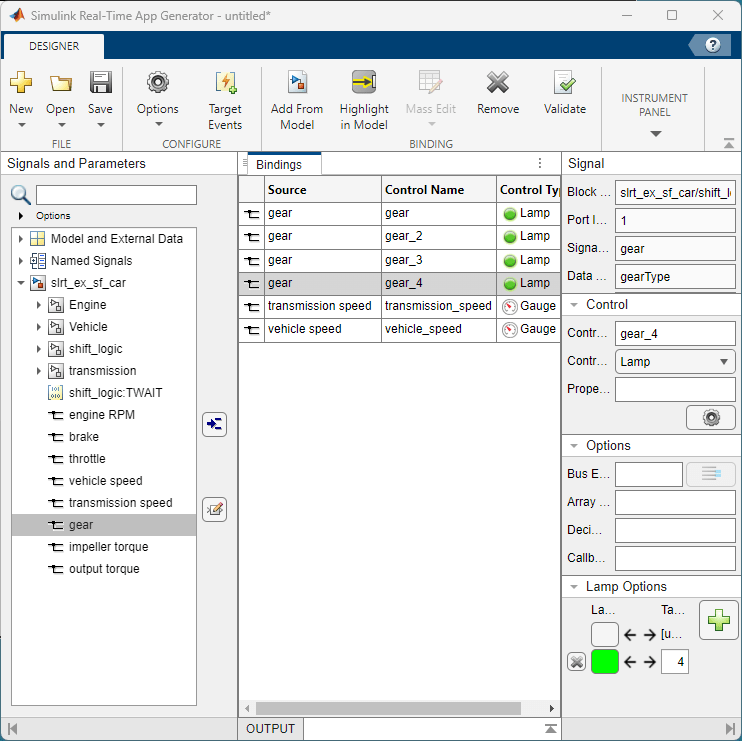
transmission speedrow in the Bindings tab. In the Property panel, click on the cog icon to open the Property Inspector. Configure the Gauge control for Limits of0, 6000and set the MajorTicks and MajorTickLabels to0,1000,2000,3000,4000,5000, and6000.
The figure shows the App Generator configuration after applying these settings.
Save Generator Session and Generate Instrument Panel App
Because instrument panel development is an iterative process, it is useful to save your App Generator session as a MAT file. This operation lets you load the session into the App Generator and resume editing the app.
In the App Generator, click the Save button and select a MAT file name for the saved session. If you need to resume editing the app generation, you can use the Open button to open this MAT file.
To generate the instrument panel MLAPP file, click the Generate App button. Enter
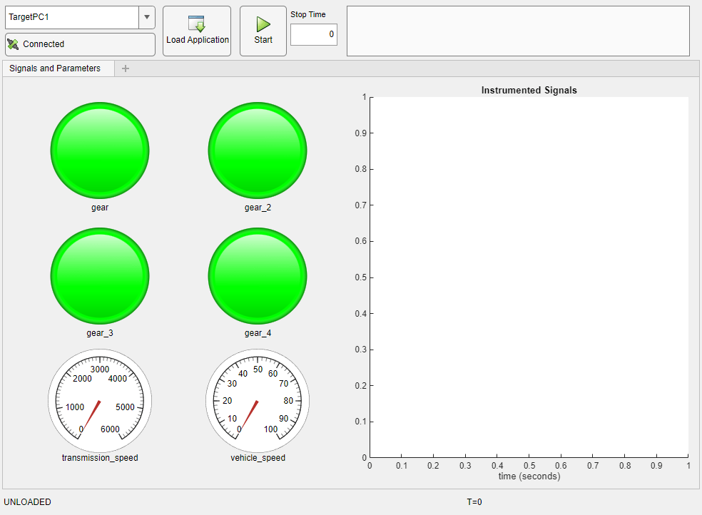
slrt_ex_sf_car_InstrumentPanelas the MLAPP file name.After generating the app, select Open in App Designer from the Success dialog box.
This figure shows the initial layout of the instrument panel in App Designer.
Edit Instrument Panel App and Add More Controls
After adjusting the layout of instrument panel controls in the App Designer and adding labels for the controls, the instrument panel is easier to use.
To make this instrument panel more informative, you can add additional controls, such as a Gauge for the vehicle speed in miles per hour (MPH) and Edit boxes to display or edit the initial conditions for the simulation scenario. The conditions provide the tunable parameters for the simulation. These parameters from the Vehicle block include:
Final drive ratio
Rfd-- set byvehicledata(1)Drag friction at wheels
rload0-- set byvehicledata(2)Aerodynamic drag
rload2-- set byvehicledata(3)Wheel radius
Rw-- set byvehicledata(4)Vehicle inertia
Iv-- set byvehicledata(5)
Save the app and close App Designer. Close the App Generator session if it is still open.
Open the Simulink Real-Time App Generator by using the command
slrtAppGeneratorin the Command Window.Select New > New. Then, select the real-time application MLDATX file
slrt_ex_sf_car.mldatx.To display the vehicle speed in miles per hour (MPH) in the generated instrument panel, in the Signals and Parameters pane, select the
vehicle speedsignal from theNamed Signalsgroup and use the Add button to add this signal to the Bindings tab.Select the
vehicle speedrow in the Bindings tab. In the Property panel, click on the cog icon to open the Property Inspector and configure the Gauge control for Limits of0, 140. To add this control to the instrument panel, click the Add to App button and select the MLAPP file for the instrument panel. Click OK to remain in the App Generator. The App Generator adds the controls and ParameterTuner code for each control.To display the tunable parameters for initial conditions of the simulation, in the Signals And Parameters pane, select the
vehicledataparameter from theModel and External Datagroup and use the Add button to add five instances of this signal to the Bindings tab.Select the five
vehicledatarows in the Bindings tab. Select Mass Edit > Change control type > Parameter Table to add a parameter table control for these signals. Select Mass Edit > Change control name and set the name tovehicledatafor these controls. To add these controls to the instrument panel, select the five rows and click the Add to App button and select the MLAPP file for the instrument panel. Click OK to remain in the App Generator.Select the top
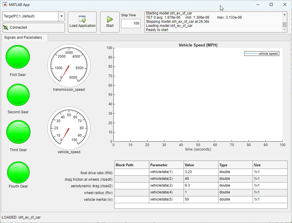
vehicledatarow in the Bindings tab. In the Properties panel, in the Options pane, set the Element field value to(1). This change makes the top row of the generated parameter table display element 1 of thevehicledataarray. This value is the final drive ratioRfd. Repeat this operation for the other fourvehicledatarows, setting these to(2),(3),(4), and(5).
The figure shows the final instrument panel after adjusting the layout for the added controls and inserting labels. When you run the instrument panel app slrt_ex_sf_car_InstrumentPanel.mlapp, the parameter table appears as shown in the figure.
Possible Next Steps
In the slrt_ex_sf_car model, you can choose from among different simulation scenarios by setting a block parameter for the User Input block. The scenarios include:
Passing_Maneuver(default)CoastingHard_brakingGradual_Acceleration
Some possible next steps for working with the model, real-time applications, and instrument panel include:
Try choosing other simulation scenarios, build multiple versions of the real-time application, and use the instrument panel to load and run these simulations.
Try using the parameter table in the instrument panel to adjust the initial conditions and re-run the simulation.
Deploy Standalone Executable App Designer Instrument Panel
From your App Designer instrument panel, you can compile a standalone executable instrument panel. For more information, see Create Standalone Instrument Panel App by Using Application Compiler.
Close App and Model
After exploring the App Designer instrument panel app and model, close all open files. In the Command Window, type:
bdclose(model);