Author a Test Sequence and Test Assessment
This example shows how to use a Test Sequence block and Test Assessment block to create a test harness for a transmission shift logic controller. The Test Sequence block varies the speed input to the controller and the Test Assessment block verifies that the speed is appropriate for the gear position. For more information, see Test Sequence Basics.
Create a Test Sequence
1. Open the model.
open_system("sf_car")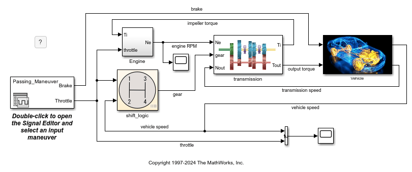
2. Right-click the shift_logic subsystem and select Test Harness > Create for ‘shift_logic’.
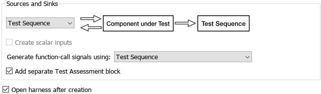
3. In the Create Test Harness dialog box, under Sources and Sinks:
Set the source drop-down menu to
Test Sequence.Select Add separate assessment block.
Select Open harness after creation.
For more information, see Create a Test Harness.
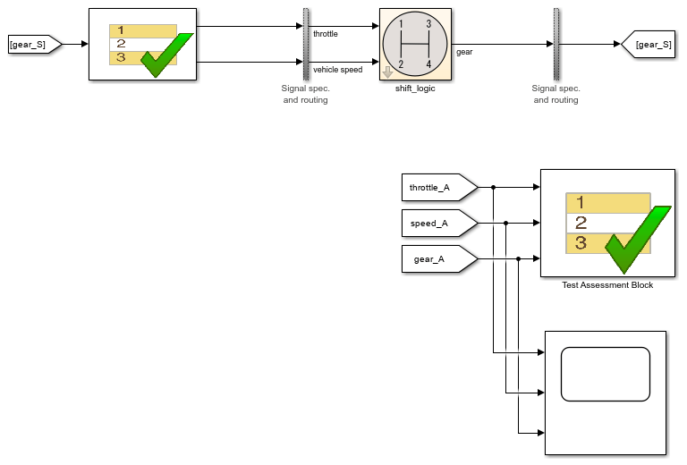
4. Click OK. The test harness for the shift_logic subsystem opens.

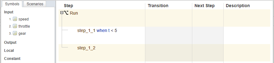
5. Double-click the Test Sequence block. The Test Sequence Editor opens.
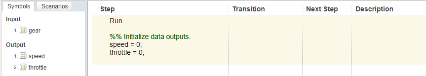
6. Change the name of the first step from Run to Accelerate, and add the step actions that specify the initial throttle setting and how the speed increases:
speed = 10*ramp(et);
throttle = 100;
The ramp function returns the value of a ramp signal of slope 1 at time et, which is the elapsed time of the step. For this example, the speed at a particular time after the beginning of the step is 10 times the value of the ramp at that time. See Test Sequence Editor for more information.
7. Right-click the Accelerate step and select Add step after. Change the name of this step from step_1 to Stop, and add the step actions that stop the test when the throttle and speed are equal to 0:
throttle = 0;
speed = 0;
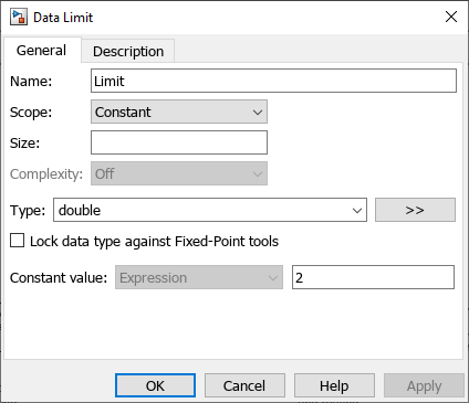
8. In the Symbols pane, point to Constant and click ![]() . Enter
. Enter Limit for the constant name and click Add data.
9. Point to Limit and click the edit button ![]() . In the Constant value field, enter
. In the Constant value field, enter 2. Click OK.
10. Right-click the Transition column in the first step, select Add transition. Enter the transition condition for the Accelerate step. In this example, Accelerate transitions to Stop when the system is in fourth gear for at least two seconds. In the Transition column, enter:
duration(gear == 4) >= Limit
11. In the Next Step column, select Stop.

12. Save the changes and close the Test Sequence Editor.
Create a Test Assessment
Next, add verifications to the Test Assessment block.
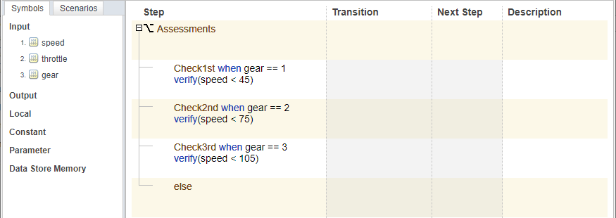
1. Double-click the Test Assessment block to open the editor. The editor displays a default When decomposition sequence in the Step column. For more information, see Activate verify Statements by Using Signal Conditions.
2. Change the name of the first step from Run to Assessments.
3. Change the names and add actions for four substeps:
Rename
step_1_1toCheck1st. Define thewhencondition asgear == 1and add averifystatement that evaluates whether the speed is less than45.Rename
step_1_2toCheck2nd. Define thewhencondition asgear == 2and add averifystatement that evaluates whether the speed is less than75.Right-click the
Check2ndstep and click Add step after. Rename the stepCheck3rd. Define thewhencondition asgear == 3and add averifystatement that evaluates whether the speed is less than105.Right click the
Check3rdstep and click Add step after. Rename the stepelse. This step handles simulation conditions outside of the precedingwhenconditions. In this step, you do not specify any actions.
4. Save the changes and close the Test Sequence Editor.
5. In the test harness, add a Scope block and connect the speed, throttle, and gear signals to the scope.
6. Open the Scope block. In View > Layout, select a three-column, one-row layout.
7. In the Simulink model, in the Simulation tab, set Stop Time to 15 and click Run. View the signal data in the Scope block. The speed plot shows how the speed increases to a maximum value of 105. The throttle plot shows that the throttle value is held at 100 throughout the test. The gear plot shows that the gear shifts to the next-higher gear at the appropriate speed. After the gear has been equal to 4 for 2 seconds, the speed and throttle go to zero and the gear decreases.

8. View the results of the verify statements in the Simulation Data Inspector.
In the Simulink model, in the Simulation tab, click Data Inspector.
Click the Visualizations and layouts button
 and, under Grid, set Rows to
 3and Columns to1.Select one plot, then select an assessment from the left pane. Repeat for each of the other plots and assessments.
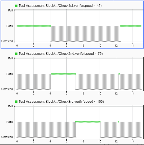
When the model runs, the Test Assessment block verifies that the speed is in the correct range for each gear position. A pass indicates that the speed is in the correct range. Each verify statement is for a specific gear, so the speed is untested when the controller is in a different gear than the one being tested. There are two pass regions for the Check1st test assessment because the gear position goes back to first in the second step of the test sequence.
See Also
Test Sequence | Test Assessment