Simulating Transients
Introduction
In this section, you
Learn how to create an electrical subsystem
Simulate transients with a circuit breaker
Compare time domain simulation results with different line models
Learn how to discretize a circuit and compare results thus obtained with results from a continuous, variable time step algorithm
Simulating Transients with a Circuit Breaker
One of the main uses of Simscape™ Electrical™ Specialized Power Systems software is to simulate transients in electrical circuits. This can be done with either mechanical switches (circuit breakers) or switches using power electronic devices.
Open the
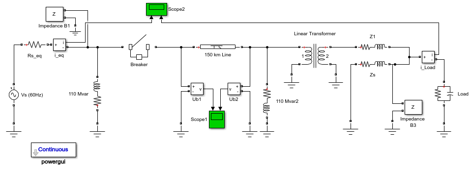
power_guiexample model.To simulate a line energization, add a Breaker block from the Simscape > Electrical > Specialized Power Systems > Passives library to the model and set the parameters as follows:.
Breaker resistance Ron (Ohm)
0.001ΩInitial status
0 (open)Snubber resistance Rs (Ohm)
infSnubber capacitance Cs (F)
0Switching times
[(1/60)/4]Insert the Breaker block in series with the sending end of the line, then rearrange the circuit as shown in the figure.

Right-click the two lines that connect to the Scope 1 block and select Properties. In the dialog box, select Log signal data for the two signals and click OK. From the Simulation Data Inspector, select Send Logged Workspace Data to Data Inspector.
Open the 150 km Line block dialog box and set the number of sections to
1. Start the simulation.Open the 150 km Line block dialog box and change the number of sections from
1to10. Start the simulation.Add a Distributed Parameters Line block from the Simscape > Electrical > Specialized Power Systems > Passives library. Set the number of phases to
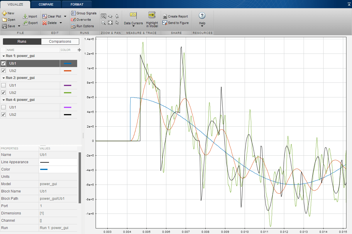
1and use the same R, L, C, and length parameters as the 150 km Line block. Delete the 150 km Line block and replace it with the Distributed Parameters Line block. Start the simulation.Compare the three waveforms obtained from the three line models. Open the Simulation Data Inspector. Select the Ub1 and Ub2 signals of Run 1, the Ub2 signals of Run 2, and Run 3.
A zoom on these waveforms is shown in the next figure. As expected from the frequency analysis performed during Analyze a Simple Circuit, the single PI model does not respond to frequencies higher than 229 Hz. The 10 PI section model gives better accuracy, although high-frequency oscillations are introduced by the discretization of the line. You can clearly see the propagation time delay of 1.03 ms associated with the distributed parameter line.
Receiving End Voltage Obtained with Three Different Line Models

Discretizing the Electrical System
An important product feature is its ability to simulate either with continuous, variable step integration algorithms or with discrete solvers. For small systems, variable time step algorithms are usually faster than fixed step methods, because the number of integration steps is lower. For large systems that contain many states or many nonlinear blocks such as power electronic switches, however, it is advantageous to discretize the electrical system.
When you discretize your system, the precision of the simulation is controlled by the time step. If you use too large a time step, the precision might not be sufficient. The only way to know if it is acceptable is to repeat the simulation with different time steps and find a compromise for the largest acceptable time step. Usually time steps of 20 µs to 50 µs give good results for simulation of switching transients on 50-Hz or 60-Hz power systems or on systems using line-commutated power electronic devices such as diodes and thyristors. You must reduce the time step for systems using forced-commutated power electronic switches. These devices, the insulated-gate bipolar transistor (IGBT), the field-effect transistor (FET), and the gate-turnoff thyristor (GTO) are operating at high switching frequencies.
For example, simulating a pulse-width-modulated (PWM) inverter operating at 8 kHz would require a time step of at most 1 µs.
Open the Neutral Point Clamp Inverter and Dead Time example. In the Powergui block, note that the Simulation type is set to
Discreteand the sample time is set to 1e-6 s by the Ts variable defined in the Model Properties. Run a first simulation.To perform a continuous simulation, open the Powergui block parameters dialog box and set Simulation type to
Continuous. Select theode23tb variable-step solverin the Configuration Parameters dialog box. Simulate the model.In the Powergui block, set Simulation type to
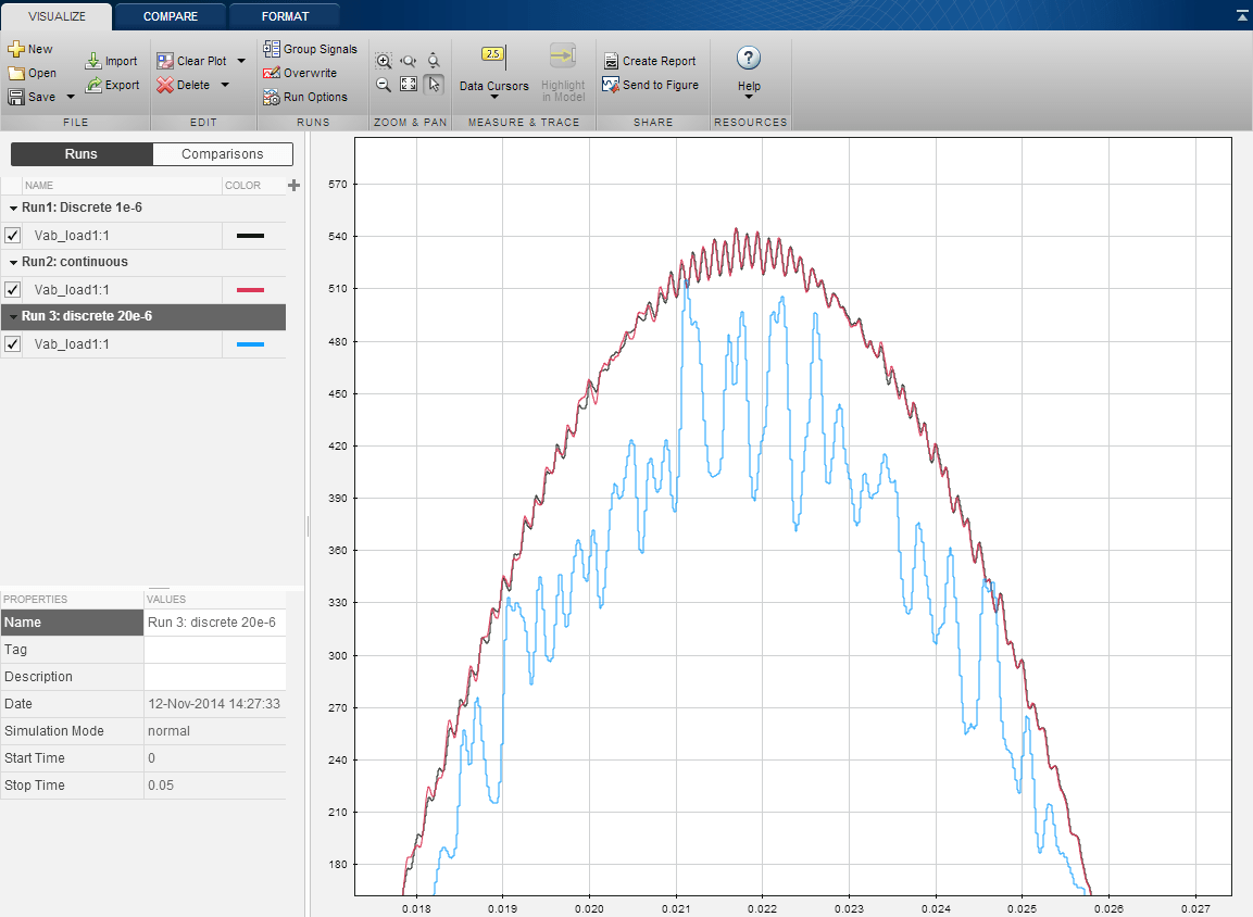
Discrete. In the InitFcn model callback section of the Model Properties, specifyTs = 20e-6. Run the simulation.Open the Simulation Data Inspector and compare the differences on the high-frequency transients.

The 1 µs compares reasonably well with the continuous simulation. However, increasing the time step to 20 µs produces appreciable errors. The 1 µs time step would therefore be acceptable for this circuit, while obtaining a gain on simulation speed.
