DC Cable
Libraries:
Simscape /
Electrical /
Passive /
Lines
Description
The DC Cable block models a DC power cable that simulates the transient response with high precision in high-voltage direct-current (HVDC) transmission applications.
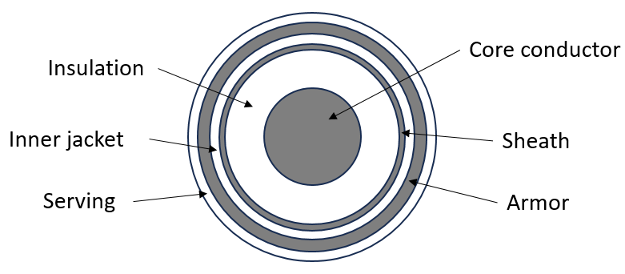
This figure shows the cross section of a cable. There are six concentric layers: core conductor, insulation, sheath, inner jacket, armor, and serving.
Equations
To obtain an accurate transient response during simulation, this block models a DC cable using a frequency-dependent modeling approach. For more information about the frequency-dependent modeling of lines, see the Equations section of the Frequency-Dependent Overhead Line (Three-Phase) block.
To use the frequency-dependent modeling approach, the block must first calculate the frequency-dependent cable parameters, such as the series impedance and shunt admittance matrices by using Dommel electromagnetic transients program (EMTP) equations. For more information about these equations, see [1].
Examples
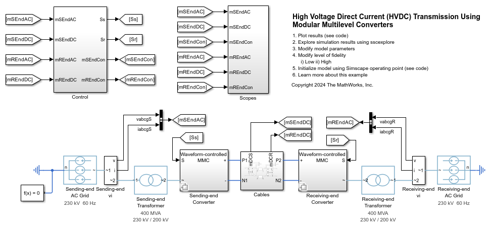
Model High-Voltage Direct-Current Transmission Using Modular Multilevel Converters
Models a high-voltage, direct-current (HVDC) transmission system using modular multilevel converters (MMC).
Ports
Conserving
Parameters
To edit block parameters interactively, use the Property Inspector. From the Simulink® Toolstrip, on the Simulation tab, in the Prepare gallery, select Property Inspector.
Main
Option to model the block as a single DC cable or double DC cables.
Resistance of the earth return.
Length of the cable.
Electrical Parameters
Resistivity of the core conductor.
Relative permeability of the core conductor.
Relative permeability of the insulation.
Relative permittivity of the insulation.
Resistivity of the sheath.
Relative permeability of the sheath.
Relative permeability of the inner jacket.
Relative permittivity of the inner jacket.
Resistivity of the armor.
Relative permeability of the armor.
Relative permeability of the serving.
Relative permittivity of the serving.
Geometric Dimensions
Radial thickness of the core conductor.
Radial thickness of the insulation.
Radial thickness of the sheath.
Radial thickness of the inner jacket.
Radial thickness of the armor.
Radial thickness of the serving
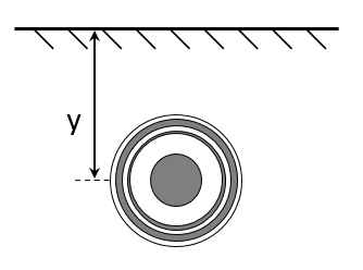
Vertical position, y, of the cable, as shown in this figure:
If you set the Configuration parameter to Double
cable, this parameter value is a vector of two positive elements,
y1 and
y2, and the default value is
[1, 1], as shown in this figure:
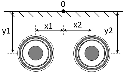
Horizontal position of the cable.
This figure shows the horizontal positions for a double cables configuration:
You specify these values with respect to the origin point. As such, these values can be positive or negative.
Dependencies
To enable this parameter, set Configuration to
Double cable.
References
[1] Dommel, Hermann W. Electromagnetic Transients Program Reference Manual: (EMTP) Theory Book. Bonneville Power Administration, 1986.
Extended Capabilities
Version History
Introduced in R2025a