Ideal Semiconductor Switch
R2026bIdeal Semiconductor Switch
Ideal Semiconductor Switch block

To add a block to a model, double-click the canvas and start typing the block name. Then, select the block from the list.
Libraries:
Simscape /
Electrical /
Semiconductors & Converters
Description
The Ideal Semiconductor Switch block models an ideal semiconductor switching device.
The figure shows a typical i-v characteristic for an ideal semiconductor switch.

If the gate-cathode voltage exceeds the specified threshold voltage, the ideal semiconductor switch is in the on state. Otherwise the device is in the off state.
In the on state, the anode-cathode path behaves like a linear resistor with on-resistance Ron.
In the off state, the anode-cathode path behaves like a linear resistor with a low off-state conductance Goff.
Using the Integral Diode parameters, you can include an integral cathode-anode diode. An integral diode protects the semiconductor device by providing a conduction path for reverse current. An inductive load can produce a high reverse-voltage spike when the semiconductor device suddenly switches off the voltage supply to the load.
Examples
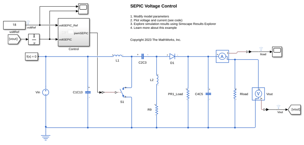
SEPIC Voltage Control
Control the output voltage of a single-ended primary-inductor converter (SEPIC). The SEPIC is a form of DC-DC converter designed to deliver a regulated positive output voltage, regardless of whether the input voltage is higher, equal to, or lower than the intended output voltage. The Control subsystem adjusts the duty cycle of the semiconductor switch to regulate the output of the SEPIC. To adjust the duty cycle, the Control subsystem uses a PI-based control algorithm. The input voltage is constant throughout the simulation. A resistor provides the load for the system. The total simulation time is 0.1 seconds.
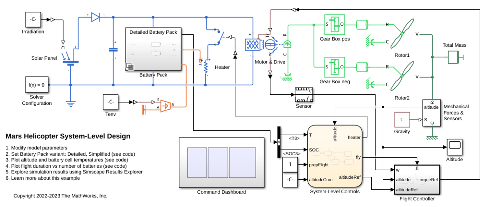
Mars Helicopter System-Level Design
Use Simscape™ Electrical™ to model a helicopter with coaxial rotors suitable to fly on Mars. This helicopter takes inspiration from Ingenuity, the robotic helicopter developed by NASA, which accomplished the first powered flight on another planet.
Assumptions and Limitations
The Ideal Semiconductor Switch block does not support energy accounting. If you try to get energy
information for this block using the getEnergyInfo function, the function generates an error message.
Ports
This figure shows the block port names.


