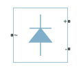
Rectifier (Three-Phase)
Uncontrolled three-phase AC to DC voltage
Libraries:
Simscape /
Electrical /
Semiconductors & Converters /
Converters
Description
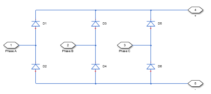
The Rectifier (Three-Phase) block models a three-arm diode bridge circuit that converts a three-phase AC voltage to a DC voltage. The figure shows the equivalent circuit for the three-arm diode bridge.
Using the Charge Dynamics tab of the block dialog box, you can choose the type of diode that the three-arm bridge circuit uses. The table shows you how to set the Model dynamics parameter based on your goals.
| Goal | Value to Select | Block Behavior |
|---|---|---|
| Prioritize simulation speed. | No dynamics | Each arm of the bridge circuit uses a copy of the Diode block. The block dialog box does not display additional parameters. |
| Precisely specify reverse-mode charge dynamics. | Model charge dynamics | Each arm of the bridge circuit uses a copy of the commutation model of the Diode block. The block dialog box shows parameters relating to the commutation model of the block. |
Examples

Composite Three-Phase Rectifier
This is the base model for analysis workflow examples.

Model 18-Pulse Diode Rectifier
Model an 18-pulse diode rectifier to reduce the line current harmonics.

Model 24-Pulse Diode Rectifier
Model a 24-pulse diode rectifier to reduce the line current harmonics.

Harmonic Analysis of a Three-Phase Rectifier
Use functions which analyze Simscape™ logging data to get harmonic magnitudes, calculate total harmonic distortion percentage and plot harmonic magnitudes. The model to which this analysis is applied is of a three-phase rectifier. The functions demonstrated are: