Serial Data Communication on F28M3x Concerto between ARM, C28x and the Host Computer
This example shows you how to use C2000™ Microcontroller Blockset for serial data exchange between the host computer and the target as well as serial data exchange between the ARM and c28x core.
In this example you will learn how to perform data exchange between the host and the target as well as between the ARM Cortex M3 and the C28x core using the serial internal loopback that exists between the two cores of the F28M3x Concerto Processor.
The F28M3x Concerto processors supports data exchange between the ARM Cortex M3 core and the C28x Core by means of a UART4 to SCI-A Internal loopback which is physical connection between the 2 peripherals. The UART4 peripheral on the ARM Cortex M3 Core and SCI-A peripheral on the C28x core need to be configured to run on the same baud rate in both the models as shown below. The Internal loopback between the UART4 AND SCI-A can be enabled from the ARM Model by browsing to Configuration Parameters > Hardware Implementation > Target hardware resources > UART4. Therefore, ensure that the UART4 baud rate matches the C28x SCI-A baud rate for internal loopback.
Prerequisites
We recommend completing the Getting Started with C2000 Microcontroller Blockset for F28M3x Concerto Processors.
Required Hardware
To run this example you will need the following hardware:
F28M36 Concerto controlCARD or
F28M35 Concerto controlCARD
The Texas Instruments ControlCARDs provide serial over USB capabilities. This allows serial communication from the target to your host computer over the USB connection to the board.
ARM Cortex M3 UART4 to C28x SCI-A Internal Loopback
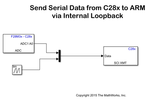
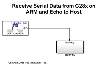
In this task, you will run a model on the C28x Core of the Concerto processor which sends data over the serial internal loopback to a model running on the ARM Cortex M3 Core. Every 1ms, 6 bytes are transmitted from C28x SCI-A to the ARM UART4 via the internal loopback. The data consists of 1 byte for packet header, 2 bytes for a 16-bit ADC value, 2 bytes for a 16-bit free-running counter and 1 byte for packet terminator. The ARM model is configured to generate an interrupt once 6 bytes are received. The UART4 serial receive block in the ARM model outputs the ADC and free-running counter values if a matching header and terminator are found. In the case where a header and terminator are not found at the right location, the block outputs values of 0 and the interrupt is resynchronized based on potential header and terminator found in the packet. In the interrupt service routine, the ADC data and the free-running counter values are sent to UART0 which is connected to the host computer. Task 2 explains this step.
1. Open the f28m35x_m3_receive.slx. This model is configured for the TI Concerto F28M35x (ARM Cortex-M3) target. To configure the model to run on TI Concerto F28M36x (ARM Cortex-M3), change the Hardware board in the Configuration Parameters > Hardware Implementation pane.
2. The Internal Loopback is enabled in Configuration Parameters -> Hardware Implementation -> Target Hardware Resources -> UART4 by setting the Enable M3 UART4 to C28 SCI-A loopback. This parameter, when enabled, physically connects UART4 on the ARM core to SCIA on the C28x core and allows serial communication between the 2 cores. The Internal loopback configuration is controlled by the ARM model and doesn't require specific settings in the C28x model. The internal loopback, being a physical connection, does not need any GPIO for communication. This enables you to select the GPIOs to None for Transmit and Receive. This allows other peripherals to use these pins.
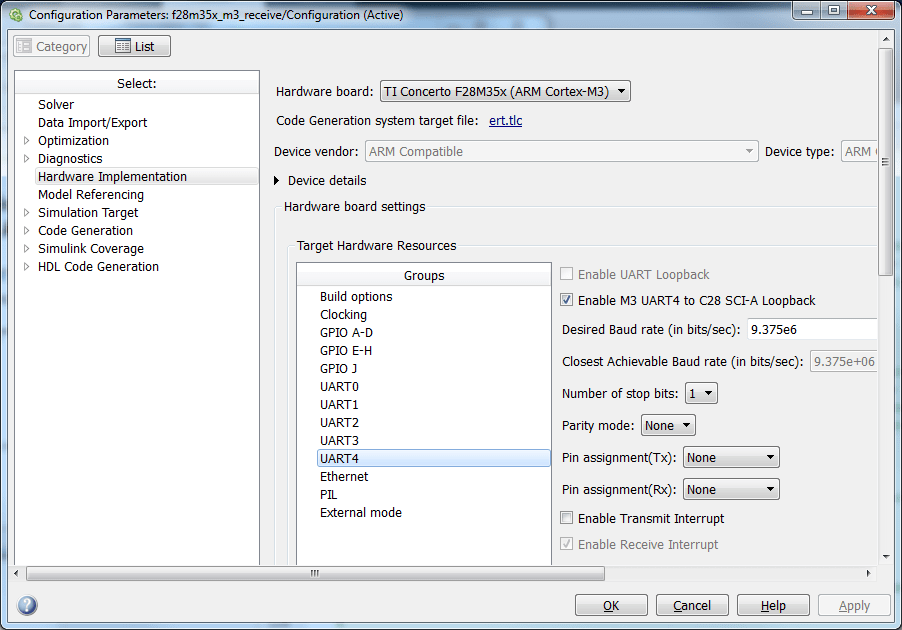
3. Configure the baud rate of the UART4 peripheral and ensure it matches the baud rate of the C28x Model SCI-A peripheral. The internal loopback allows high serial baud rates. In these example models, the baud rates are set to 9.375 Mbps, which is the maximum achievable value by the hardware.
4. Click Apply and close the configuration parameters window.
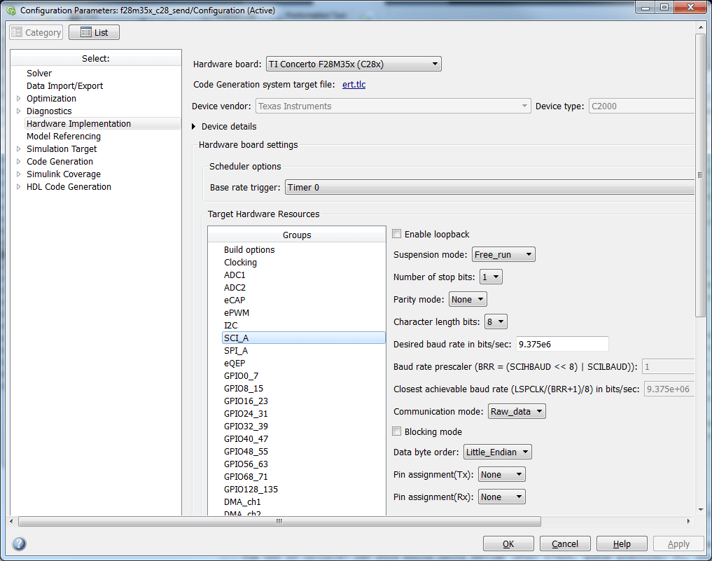
5. Open the f28m35x_c28_send.slx model. This model is configured for the TI Concerto F28M35x (C28x) target. To configure the model to run on TI Concerto F28M36x (C28x), change the Hardware board in the Configuration Parameters > Hardware Implementation pane. There are no settings for the internal loopback required on the C28x model.
6. Match the UART4 Closest Achievable Baud rate by selecting an appropriate desired baud rate for the SCI-A peripheral. 9.375 Mbps is used in this example.
7. Click Apply and close the configuration parameters window.
8. Build, load and run both the models. You can monitor the sent data through Task 2 and verify that the models are running correctly.
Sending Data to the Host Computer
The Model running on the ARM Core transmits data to the host computer via UART0. You can access UART0 data on your host computer, via the USB cable connected to the controlCARD through a virtual COM port. For more information on how to configure the virtual COM port, refer to this page. Note the virtual COM port number of the USB Serial Port showing in your Windows Device Manager under Ports "(COM & LPT)", you will need it to configure your host receive program.
1. The ARM model sends data to the host via UART0 peripheral every 1ms. The turnaround time of Simulink does not allow code running on the host computer to receive data at that rate. The host computer can work on large data sets coming at a slower pace. The ARM model is constructed to add a header and terminator every 60ms. The host computer program will expect 244 bytes to be present in the serial buffer every 60ms. This technique works best with Simulink.
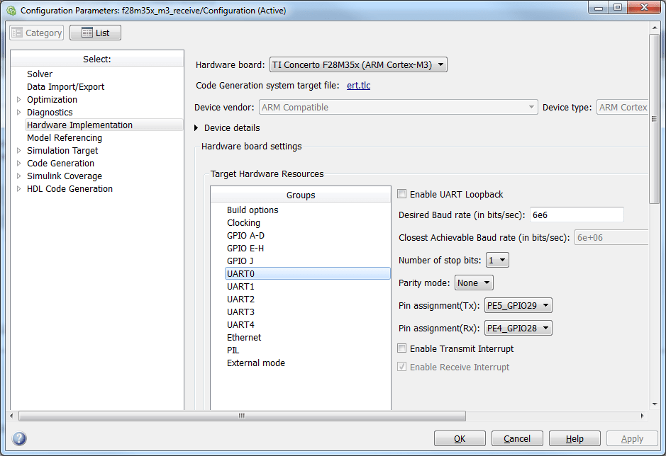
2. The serial over USB capability of the Concerto controlCARDs allows a maximum baud rate of 6Mbps. You can configure the baud rate and the GPIOs used for the serial connection on the UART0 pane of the Configuration Parameters -> Hardware Implementation tab. This example model uses a baud rate of 6Mbps along with PE5_GPIO29 and PE4_GPIO28 for transmit and receive respectively over UART0. These pins are connected to the serial over USB device present on the controlCARD.
3. You can read and plot the data using the Host Model. This model requires DSP System Toolbox and Instrument Control Toolbox. On the host model, enter the virtual COM port number and the baud rate in the Serial Configuration block. In the Serial Receive block, match the COM port number with the virtual COM port number. The Header and Terminator match with values specified in the f28m35x_m3_receive.slx Note that the length and the sample time will ensure that the simulation will get a new frame every 60ms, although the ARM UART model sends a fresh data point every millisecond. This ensures that the simulation turnaround time is sufficient on the host. While Simulink can easily get one frame of 244 bytes every 60ms, it can not turnaround at a 1ms rate on a host computer and get one set of samples at a time. The model creates a variable named serial_received_data in the workspace that you can use to view and analyze the data. Note that MATLAB is set to use row-major order while the target uses column-major order which explains the need to transpose the data received with the Serial Receive block.
Open Host_read_f28m35.slx host model

Things to remember while setting up the model
Make sure that the closest achievable baud rate of UART 4 peripheral in the ARM Cortex M3 Model and in the SCI-A peripheral on the C28x model are matching.