Define Virtual Vehicle Components: Passenger Vehicle
Use the Virtual Vehicle Composer to define the components in your chosen vehicle architecture. In the Data and Calibration pane, make selections for the body and frame, suspension, tires, powertrain, environment, and so forth.
The Virtual Vehicle Composer model template starts with a set of default components, as shown in the Data and Calibration pane. The component types are listed in the menu tree on the left side of the pane. You can choose and parameterize specific components on the right side.
For each component type, you can specify it in one of two ways:
From a list within the Virtual Vehicle Composer, select an available component and modify its parameters. Depending on the component, you can enter different parameters, load a file containing different parameters, or use a resize option.
If Model template is set to
Simulink, you can choose a component using the Custom component catalog. This is an XML file that points to custom components stored externally to the app. These custom components can be modified Virtual Vehicle Composer components or externally created Simulink models that are compatible with Virtual Vehicle Composer.
The component options depend on the products installed and your Setup selections.
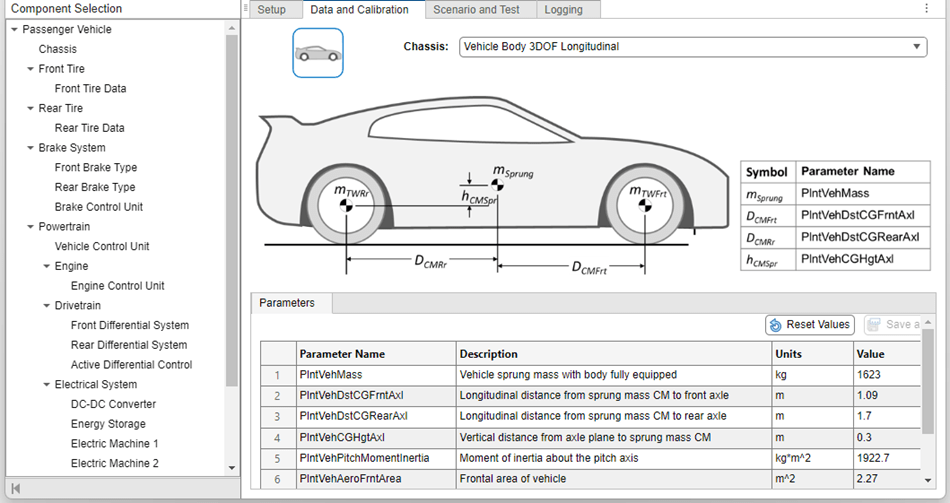
Body and Frame
The Body and Frame section includes parameters associated with the body of the vehicle, such as the sprung mass and its center of mass (CM), moments of inertia, wheelbase and track width, and aerodynamic force coefficients.
These assumptions apply to the passenger vehicle chassis:
The body and frame assembly is rigid. All components mounted to the body/frame are rigidly attached.
The sprung mass includes all components mounted to the body, and the height of its center of mass (CM) is specified relative to the axle plane.
The unsprung mass for each wheel location is the sum of the tire, wheel, brakes, and moving parts of the suspension. Set the tire mass equal to their sum in the Front Tire and Wheel and Rear Tire and Wheel sections.
Steering System
If Vehicle dynamics is set to Combined
longitudinal and lateral dynamics, you can specify the steering system
type and parameters.
If you set Model template to
Simulink, you can choose from three options for
Steering system:
Kinematic Steering— Calculate the steered wheel angles based on a steering ratio and Ackerman percentage, with no system compliance.Mapped Steering— Use a rack and pinion system where the steered wheel angles are mapped to the steering wheel rotation and rack displacement, with no system compliance.Steering System— Incorporate the geometry of a rack and pinion system that also includes compliance, friction, and power assist.
With Model template set to
Simscape, you have one choice for Steering
system:
Multibody Steering System— Incorporate rack and pinion geometry in a Simscape™ Multibody™ Link model. This option does not include system compliance.
Front and Rear Suspensions
If Vehicle dynamics is set to Combined
longitudinal and lateral dynamics, you can specify the suspension
types and parameters.
With Model template set to
Simulink, you have two choices for Front
Suspension:
Kinematics and Compliance Independent Suspension
                            Front
MacPherson Front Suspension
With a Model template set to
Simulink, you have three choices for Rear
Suspension:
Kinematics and Compliance Independent Suspension
                            Rear
Solid Axle Rear SuspensionKinematics and Compliance Twist Beam Suspension Rear
The kinematics and compliance options use output from a kinematics and compliance test machine or from a more detailed model.
With Model template set to
Simscape, you have only one option each for the front and
rear axles:
Simscape Suspension FrontSimscape Suspension Rear
These options are double-wishbone suspensions modeled in Simscape Multibody Link without joint compliance.
Tire and Wheel Systems
Select tire and wheel systems separately for the front and rear axles. Tire properties are modeled by equations whose parameters must be fit as a set. The available options depend on the Vehicle dynamics and the Model template selected. The choices are the same front to rear.
In all cases, to account for the unsprung mass at each wheel location, set the tire mass in the Front Tire and Wheel and Rear Tire and Wheel sections equal to the sum of the tire, wheel, brakes, and moving components of the suspension.
With Model template set to
Simulink and Vehicle dynamics
set to Longitudinal dynamics, you have two Front
Tire and Wheel options:
MF Tires Longitudinal FrontCombined Slip Tires Longitudinal Front
You have two options for Rear Tire and Wheel:
MF Tires Longitudinal RearCombined Slip Tires Longitudinal Rear
These options use the Magic Formula introduced by Pacejka. The MF Tires
Longitudinal Front and MF Tires Longitudinal
Front options include options for modifying rolling resistance.
With Model template set to
Simulink and Vehicle dynamics
set to Combined longitudinal and lateral dynamics, you have
two options for Front Tire and Wheel:
MF Tires Longitudinal and Lateral Front, which uses the Magic FormulaFiala Tires Longitudinal and Lateral Front, which uses a Fiala tire model
You have two options for Rear Tire and Wheel:
MF Tires Longitudinal and Lateral Rear, which uses the Magic FormulaFiala Tires Longitudinal and Lateral Rear, which uses a Fiala tire model
With Model template set to
Simscape and Vehicle dynamics
set to Longitudinal dynamics, you have one option for
Front Tire and Wheel:
MF Tires Longitudinal Front, which uses the Magic Formula
And one option for Rear Tire and Wheel:
MF Tires Longitudinal Rear, which uses the Magic Formula
With Model template set to
Simscape, and Vehicle dynamics
set to Combined longitudinal and lateral dynamics, there is
one option for Front Tire and Wheel:
Simscape MF Tires Front, which uses the Magic Formula in a Simscape representation
You have one option for Rear Tire and Wheel:
Simscape MF Tires Rear, which uses the Magic Formula in a Simscape representation
Brake System
The brake system consists of the hardware on the front and rear axles, and options for an anti-lock braking system (ABS) and a traction control system (TCS).
With Model template set to
Simulink, you have three choices each for
Front Brake Type and Rear Brake
Type:
DiscDrumMapped
For the Disc and Drum options,
the model uses the physical parameters of the brake mechanism to calculate braking
torque as a function of brake fluid pressure. For the Mapped
option, the braking torque is a mapped function of wheel rotation speed and brake fluid
pressure.
With Model template set to
Simscape, you have one choice each for Front
Brake Type and Rear Brake Type:
Disc
With either setting for Model template, you have three choices for Brake Control Unit:
Open LoopBang Bang ABSFive-State ABS and TCS
The Open Loop option applies brake fluid pressure based on
driver command and bias settings, with no control unit. The Bang Bang
ABS option implements an ABS feedback controller that regulates tire
slip by switching fluid pressure between two states at each wheel, to hold slip at its
maximum traction value. The Five-State ABS and TCS option
operates similarly, but uses logic-switching based on wheel deceleration and vehicle
acceleration to modulate the braking pressure at each wheel to control slip. This option
also provides traction control.
Vehicle Control Unit
Passenger vehicles with battery-electric and hybrid-electric powertrains use a vehicle control unit (VCU) to manage the energy used by the electric motors and discharged or stored by the battery.
The powertrain architecture uniquely determines the vehicle control unit setting. For
example, if Powertrain architecture is set to
Electric Vehicle 1EM, then Vehicle control
unit is EV 1EM with BMS.
Engine and Engine Control Unit
Depending on the powertrain architecture, you have up to twelve options for Engine:
Four spark-ignition (SI) engines fueled by gasoline
Four spark-ignition engines fueled by hydrogen
Three compression-ignition (CI) engines fueled by diesel fuel
An FMU engine
The engines are modeled in several ways:
SI Mapped Engine,SI H2 Mapped Engine, andCI Mapped Engineuse detailed look-up tables from steady-state operation. The data inputs include power, air mass flow rate, fuel flow, exhaust temperature, efficiency, and emission performance.SI Simple Engine,SI H2 Simple Engine, andCI Simple Engineestimate engine torque and fuel flow rate using a steady-state table of maximum torque versus engine speed, along with two scalar fuel mass properties, and one scalar engine efficiency parameter.SI Engine,SI H2 Engine, andCI Enginephysically model the engine from intake port to exhaust port, including transient operating conditions. These models take into account the ambient values of atmospheric temperature and pressure.SI Deep Learning EngineandSI H2 Deep Learning Engineuse a deep learning model that is generated from transient training data. This model type is capable of responding to rapid changes in operating conditions.FMU Engineuses an FMU (functional mockup unit) model that you supply.
Each engine has an engine control unit (ECU). The Engine Control Unit is automatically set to the appropriate type for the Engine selected:
Simple ECUforSI Simple Engine,SI H2 Simple Engine,CI Simple Engine, andFMU Engine.SI Engine ControllerforSI Mapped Engine,SI Engine,SI Deep Learning Engine,SI H2 Mapped Engine,SI H2 Engine, andSI H2 Deep Learning EngineCI Engine ControllerforCI Mapped EngineandCI Engine
DC-DC Converter
Powertrains with one or more electric motors include a DC-DC converter to convert battery voltage to the desired motor voltage. You have two options for DC-DC Converter:
DC-DC Converter, a bidirectional DC-to-DC converter that supports boost (voltage-increasing) and buck (voltage-reducing) operationsHVDCPassThrough, which supplies current at battery voltage
Energy Storage
Powertrains with one or more electric motors include a battery to store electrical energy. For Energy Storage, you have two options:
Mapped Battery (your application)Ideal Voltage Source
In mapped batteries, open-circuit voltage and internal resistance are mapped functions of the state-of charge (SOC) and battery temperature. The ideal voltage source is a constant-voltage source that represents an infinite storage capacity.
Electric Motors
Battery-electric and hybrid-electric powertrains use one or more electric motors. The electric motors used in Virtual Vehicle Composer are synchronous AC permanent magnet electric machines, modeled as mapped motors.
For each electric motor in your powertrain — Electric Machine 1, Electric Machine 2, and so forth — the default motor is sized for your application. You have a choice of two motor types:
Simple Motor, which maps electrical losses as a function of speed and torqueMapped Motor, which maps electrical losses as a function of torque, speed, voltage, and temperature
The name for each motor option includes its application and type. For example, if
Powertrain architecture is set to Hybrid
Electric Vehicle IPS, then the choices for Electric
Machine 1 are:
Hybrid Electric Vehicle IPS - Simple MotorHybrid Electric Vehicle IPS - Mapped Motor
Thermal System
The Virtual Vehicle Composer has a thermal system option for battery-electric powertrains to manage the temperatures of the electrical components.
The thermal system model depends on whether you set Model
template to Simulink or
Simscape. The Simulink® model acts as a surrogate for the thermal management subsystem and can be
rapidly parameterized and calibrated using either test data or high-fidelity fluid
dynamics results. By leveraging heat flow rates and coefficients of performance, the
model estimates battery load with sufficient accuracy. The Simscape model has thermal nodes for the battery, motor, and cabin, along with
coolant loops that can be configured in series or parallel and a refrigeration loop.
This enables cabin HVAC with heat pump mode and provides heating or cooling for the
electric powertrain. The thermal system uses a Stateflow® controller to regulate the battery, motor, and cabin target temperatures
to specified targets.
Switching a four-way valve toggles the loops between series and parallel modes, and bypass valves can divert flow around the heat exchangers.
The figure shows parallel operation with no bypassing.
The figure shows series operation with no bypassing.
Drivetrain
The drivetrain distributes power to the driven wheels by some combination of interconnections, differentials, and individual electric motors.
Depending on the selection for Powertrain architecture, the options for Drivetrain are:
Front Wheel DriveRear Wheel DriveAll Wheel DriveAll Wheel Driven by 2EMAll Wheel Driven by 3EM FrontAll Wheel Driven by 3EM RearAll Wheel Driven by 4EM
For Front Wheel Drive, the drivetrain drives both wheels on
the front axle through a differential. For Rear Wheel Drive,
the drivetrain drives both wheels on the rear axle through a differential. For
All Wheel Drive, the drivetrain drives all four wheels
through a transfer case, and differentials on both axles. These three options apply when
the power comes from a single propulsion unit, such as an internal combustion engine, a
hybrid powertrain, or a single electric motor.
If Drivetrain is set to All Wheel
Drive and has a single power input, then Axle
Interconnect defaults to Transfer Case. It
includes an open differential and an adjustable torque split between front and rear
axles.
The last four Drivetrain options are battery-electric powertrains providing all wheel drive in different ways:
All Wheel Driven by 2EMuses a single motor driving the front wheels through a differential and a single motor driving the rear wheels through a differential.All Wheel Driven by 3EM Frontuses two motors driving the front wheels separately and a single motor driving the rear wheels through a differential.All Wheel Driven by 3EM Rearuses two motors driving the rear wheels separately and a single motor driving the front wheels through a differential.All Wheel Driven by 4EMuses a single motor driving each wheel separately.
For each of these four options, the powertrain architecture uniquely determines the
Drivetrain setting. For example, setting
Powertrain architecture to Electric Vehicle
3EM automatically sets Drivetrain to
All Wheel Driven by 3EM Front. Also, these four all wheel
drive options have no mechanical connection between front and rear axles, so
Axle Interconnect does not appear as an option.
Transmission and Transmission Control Unit
Depending on the Powertrain architecture setting, you may have a choice of Transmission:
Ideal Fixed Gear Transmissionis an idealized transmission without clutch or synchronization detail. Use this setting to model the gear ratios and power loss when you do not need a detailed transmission model.Automatic Transmission with Torque Converteruses planetary gears.Automated Manual Transmissionis a manual transmission with additional actuators and an electronic control unit (ECU) to regulate clutch and gear selection based on commands from a controller. Clutch and synchronizer engagement rates are linear and adjustable.
The only choice for Transmission Control Unit is
PRNDL Controller. The controller commands forward,
reverse, neutral, park, and N-speed gear shifts according to the
selected shift schedule.
Final Drive
If you set Drivetrain to Front Wheel
Drive or All Wheel Drive, you see these
options for Front Differential System:
Open DifferentialLimited Slip Differential
If you set Drivetrain to Rear Wheel
Drive or All Wheel Drive, you see these
options for Rear Differential System:
Open Differential RearLimited Slip Differential RearActive Differential Rear, only if Model Template is set toSimulink
If you set Rear Differential System to Active
Differential Rear, you have two options for the Active
differential control:
No ControlRear Differential Controller
In architectures where two motors drive the wheels on an axle separately, that is what
provides differential action. For example, with Powertrain
architecture set to Electric Vehicle
4EM:
Front Differential System is set to
Dual EM Drive Front.Rear Differential System is set to
Dual EM Drive Rear.
Trailer
The Virtual Vehicle Composer can attach a one-axle trailer to your
Passenger vehicle. You have these options for
Trailer:
No TrailerOne-Axle Trailer
Environment
Use the Environment parameter to set the ambient air, wind, and road conditions for your tests.
The app uses the ambient absolute air pressure and absolute air temperature in the ideal gas law to calculate air density, which the app then uses to calculate aerodynamic forces. Also, these Engine types take air density into account when calculating engine performance:
SI EngineSI H2 EngineCI Engine
Other Engine types do not adjust their performance for ambient conditions. Their performance is calculated for temperature and pressure conditions of 293.15 kelvins and 101,325 pascals.