Track Marker Using Simulink Images
This example shows how to track a marker on a whiteboard by using images of the Simulink.ImageType data type.
Example Model
The ex_tracking_marker example model contains a model reference hierarcy. Each model contributes towards the image processing algorithm.
ex_tracking_marker- Top model that tracks a marker in an input video. This model renders the output video by using the Video Viewer block and the logs the output frame in theout.MarkerOnImageworkspace variable.
ColorTracking- Referenced model that implements a basic image thresholding algorithm. IncludesProcessFramesForMarkerprocesses the centroid of each frame. TheDrawMarkerssubsystem plots the line from the centroid of the previous frame to the current frame.
ProcessFramesForMarker- Referenced model that looks for pixels in each frame and localizes the centroid in every frame. The MATLAB Function blockDetectMarkeruses the thresholding logic and the MATLAB Function blockFindContourslocalizes the centroid of the detected pixels.
![]()
Working with Simulink Images
A Simulink.ImageType data type is an encapsulated object that defines an image with fixed meta-attributes specific to this data type. The ex_tracking_marker model takes the input video through From Multimedia File block as a Simulink image by setting the block parameter Image signal to Simulink image signal.
If your image processing algorithm includes blocks that currently don't support the Simulink.ImageType data type, use the From Simulink Image block to unpack data in from the Simulink image to a matrix. Specify the block parameter Output dimensions as [720 960 3] which corresponds to the rows, columns, and channels in the image. Because MATLAB Function blocks operate on matrix data only, the ColorTracking model uses a From Simulink Image block before passing the image data to the ProcessFramesForMarker model, which contains MATLAB Function blocks. To review these configurations, open the ColorTracking model.
![]()
The DrawMarkers subsystem draws the tracking line on the image, and converts the image from matrix format to a Simulink image by using the To Simulink Image block. This image is then fed to the Video Viewer block. To review these configurations, open the ProcessFramesForMarker model.
![]()
Simulate Model
To simulate the model, on the Simulink toolstrip, in the Simulation tab, select Run. The Video Viewer block opens and displays the tracker tracing the marker. The simulation runs at a reduced pace so you can observe the real-time behavior of the system. To change the pacing of the model, select Run > Simulation Pacing.
To generate a final image that draws over the logged outputs, in the MATLAB Command Window, run these commands.
vw = VideoWriter('WhatDidIDraw.mp4');
vw.open();
h=figure;
Ax = axes(h);
for i = 2:70
    imshow(out.yout{1}.Values.Data(:,:,:,i),'Parent',Ax);
    drawpolyline('Position',transpose(squeeze(out.yout{2}.Values.Data(:,:,1:i))),'StripeColor','blue','Parent',Ax);
    vw.writeVideo(getframe(h));
end
vw.close();
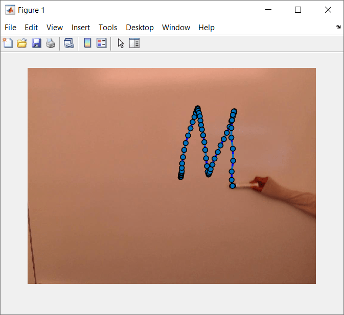
Results
The script uses the logged output video to generate the path the marker followed and displays the result in the Video Viewer block.