Implement Distributed ECU Network over CAN in Simulink
This example shows you how to use Vehicle Network Toolbox™ and Simulink® to implement a distributed Electronic Control Unit (ECU) network over CAN for an automobile.
Vehicle Network Toolbox provides Simulink blocks for transmitting and receiving live messages via Simulink models over Controller Area Networks (CAN). This example uses the CAN Configuration, CAN Pack, CAN Transmit, CAN Receive, and CAN Unpack blocks to perform data transfer over a CAN bus.The CAN messages are defined in the CAN database file, canConnectivityForVehicle.dbc.
This example uses MathWorks® virtual CAN channels. However, you can connect your models to other supported hardware.
Model Description

The model consists of the following subsystems: Vehicle dynamics model, Sensors and actuators, Turn signal, Dashboard, brake light and Speed controller. The Vehicle dynamics model represents the automobile (the environment), and the other subsystems represent the various nodes on the CAN bus.
Vehicle Dynamics Model
This subsystem defines the equations of motion of the automobile. The inputs are the throttle and brake actuator positions. The outputs are the engine RPM and vehicle speed, that are multiplexed into a single signal.
Sensors and Actuators
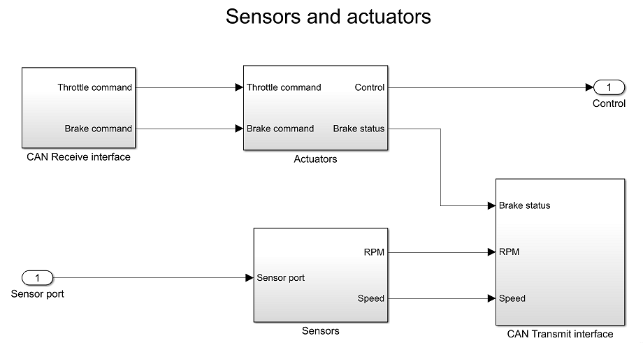
This subsystem consists of the throttle and brake actuators, and the RPM and vehicle speed sensors. The actuators receive the throttle and the brake commands via the CAN bus. The actuator outputs (control) are fed to the vehicle dynamics model.
The brake actuator also sends a signal that informs whether or not the brakes are actuated. This signal is sampled at 100 Hz and transmitted into the CAN bus. The engine RPM and vehicle speed signals from the vehicle dynamics model that are input to this subsystem and are also sampled at 100 Hz and transmitted into the CAN bus.
Dashboard
The dashboard is the interface between the vehicle and the driver. The commanded speed can be set by the user using the slider (Speed command:Value). The turn signal can be operated using the rotary switch (Turn signal:Value).
The speed command and turn signal status signals are transmitted into the CAN bus. The sampled vehicle speed and engine RPM are read from the CAN bus and displayed on the speedometer and the tachometer respectively.
Speed Controller
The speed controller sends commands to the actuators to drive the vehicle speed to the commanded value. The vehicle speed and the commanded speed are read from the CAN bus. The throttle and brake commands are calculated by the corresponding discrete Proportional - Integral controllers. The actuator commands are transmitted into the CAN bus.
Brake Light
The Brake light subsystem receives the brake actuator status signal from the CAN bus and appropriately operates the brake lights. Whenever the brakes are actuated, the brake lights are turned on.
Turn Signal
The turn signal subsystem receives the turn signal status message from the CAN bus and appropriately activates the turn signals. The left turn signal light blinks periodically when the rotary switch is set to the "Left" position, and the right turn signal light blinks periodically when the rotary switch is set to the "Right" position.