Pulse Radar Scenario Using Target Emulator on NI USRP Radio
This example shows how to run a pulse radar scenario on an NI™ USRP™ radio with a target emulation algorithm deployed on the FPGA.
Associated Radar Target Emulation Examples
This example is one in a group of related examples that demonstrate how to use a radar target emulation design running on the FPGA of an NI USRP radio in different deployment scenarios. For more information, see Radar Target Emulation Applications Overview.
Introduction
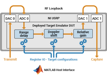
In this example, you use the target emulation algorithm from the Radar Target Emulation on NI USRP Radio example deployed on the FPGA to run a pulse radar scenario. The target emulation design under test (DUT) receives a linear FM pulse train and emulates up to eight targets by applying variable range delays, Doppler shifts, and gains to the received waveform. Then, the algorithm retransmits the modified waveform at a known time offset. You use the same radio to transmit a radar pulse train to exercise the DUT, and to capture the retransmitted waveform for analysis in MATLAB®.
You follow these steps:
Set up the target emulation scenario using Radar Toolbox™.
Set up and configure the radio with the generated bitstream and interfaces.
Configure additional radio antennas for transmit and capture from the host.
Configure the target emulation DUT with the initial scenario conditions.
Schedule the transmission of a radar pulse train.
Schedule the streaming of IQ samples from the air into the onboard memory.
Plot the range-Doppler response for the samples received to the host.
Update the scenario and the target emulation parameters on the hardware.
Repeat steps 5 to 8 until the scenario is complete.
Prerequisites
This example uses the target emulator bitstream from the Radar Target Emulation on NI USRP Radio example. Before you run this example, follow these steps:
Run the Radar Target Emulation on NI USRP Radio example to generate a bitstream for the target emulation design, deploy the bitstream on the FPGA, and verify the design running on your radio.
Open this example in MATLAB by using the
openExamplefunction:openExample("wt/RADARTargetEmulatorWithSingleNIUSRPRadioExample")Copy these files into the new example working directory:
The hand-off information file,
wtRadarTargetEmulatorSL_wthandoffinfo.matThe bitstream (
.bit) and device tree (.dts) file, which are generated in the project folderThe generated host interface setup function fil,:
gs_wtRADARTargetEmulatorSL_setup.m
Set Up Radar Scenario
Create a platform (Radar Toolbox) object with an update rate of 500 ms and run the scenario for 60 frames to advance the eight targets through a simple simulation.
nSteps = 60;
tUpdate = 0.5;
tRun = nSteps*tUpdate;
scenario = radarScenario(UpdateRate=1/tUpdate,StopTime=tRun);
Set the radar position to the origin.
radarPosition = [0 0 0];
Import the mean radar cross-section (RCS) for a Boeing® 737 and assign it to an RCS signature object. Use this RCS for each of the targets to model them as aircraft.
load('RCSSignatureExampleData.mat','boeing737');
planeRcsSignature = rcsSignature( ...
    Pattern=boeing737.RCSdBsm, ...
    Azimuth=boeing737.Azimuth, ...
    Elevation=[-90 90]);
Add each target to the scenario as a platform (Radar Toolbox) object with a unique trajectory and the imported aircraft RCS signature.
Use the kinematicTrajectory (Navigation Toolbox) function to set the location of the first target at 5 km ground range, 2 km height, moving away from the radar at 200 m/s.
t1Pos = [5e3 0 2e3];
t1Vel = [200 0 0];
t1 = platform(scenario);
t1.Signatures = {planeRcsSignature};
t1.Trajectory = kinematicTrajectory(Position=t1Pos,Velocity=t1Vel);
Set the location of the second target at 7.5 km ground range, 1 km height, moving towards the radar at 150 m/s.
t2Pos = [7.5e3 0 1e3];
t2Vel = [-150 0 0];
t2 = platform(scenario);
t2.Signatures = {planeRcsSignature};
t2.Trajectory = kinematicTrajectory(Position=t2Pos,Velocity=t2Vel);
Set the location of the third target to diagonal (7.5 km in x, 3 km in y), 2.5 km height, flying in a straight line so that radial velocity changes constantly.
t3Pos = [7.5e3 3e3 2.5e3];
t3Vel = [0 -250 0];
t3 = platform(scenario);
t3.Signatures = {planeRcsSignature};
t3.Trajectory = kinematicTrajectory(Position=t3Pos,Velocity=t3Vel);
Use the circular waypoint helper function to set the fourth target flying in a circle around the radar at 4 km, so that the radial speed is always 0.
t4Dist = 4e3;
t4 = platform(scenario);
t4.Signatures = {planeRcsSignature};
t4.Trajectory = helperRadarTargetCircularWaypoints(t4Dist,radarPosition,tRun);
Use the kinematicTrajectory function to set the location of the fifth target at 3 km ground range, 400m height, moving away from the radar at 180 m/s.
t5Pos = [3e3 0 0.4e3];
t5Vel = [180 0 0];
t5 = platform(scenario);
t5.Signatures = {planeRcsSignature};
t5.Trajectory = kinematicTrajectory(Position=t5Pos,Velocity=t5Vel);
Set the location of the sixth target at 800 m ground range, 800 m height, moving away from the radar at 90 m/s.
t6Pos = [0.8e3 0 0.8e3];
t6Vel = [90 0 0];
t6 = platform(scenario);
t6.Signatures = {planeRcsSignature};
t6.Trajectory = kinematicTrajectory(Position=t6Pos,Velocity=t6Vel);
Set the location of the seventh target to diagonal (350m in x, 1 km in y), 2.5 km height, flying in a straight line so that the radial velocity changes constantly.
t7Pos = [0.35e3 1e3 2.5e3];
t7Vel = [0 100 0];
t7 = platform(scenario);
t7.Signatures = {planeRcsSignature};
t7.Trajectory = kinematicTrajectory(Position=t7Pos,Velocity=t7Vel);
Use the circular waypoint helper function to set the eighth target flying in a circle around the radar at 9 km, so that the radial speed is always 0.
t8Dist = 9e3;
t8 = platform(scenario);
t8.Signatures = {planeRcsSignature};
t8.Trajectory = helperRadarTargetCircularWaypoints(t8Dist,radarPosition,tRun);
Customize the simulation by editing the helperRadarTargetSimulationSetup helper function. Update the sample rate (Fs) and center frequency (Fc) for your radio hardware.
Run the target simulator setup helper function to get the default simulation parameters. You update the simulation parameters for each of the targets in a later step.
sim_in = helperRadarTargetSimulationSetup();
Select Radio
Call the radioConfigurations function. The function returns all available radio setup configurations that you saved using the Radio Setup wizard.
savedRadioConfigurations = radioConfigurations;
To update the menu with your saved radio setup configuration names, click Update. Then select the radio to use with this example.
savedRadioConfigurationNames = [string({savedRadioConfigurations.Name})];
radioName = savedRadioConfigurationNames(1);
Evaluate the transmit and receive antennas available on your radio device. You use these values to configure transmit and capture antennas later in the script.
availableReceiveAntennas = hCaptureAntennas(radioName);
availableTransmitAntennas = hTransmitAntennas(radioName);
Create a radio object. This object enables you to synchronize transmit and receive operations.
radio = radioConfigurations(radioName);
Create usrp System Object
Create a usrp System object™ with the radio object. This System object controls the radio hardware.
device = usrp(radio);
Program FPGA
If you have not yet programmed your device with the bitstream, select the program bitstream option. Update the code with your bitstream and hand-off information files. You can find these files in generated the host interface script, gs_wtRADARTargetEmulator_interface. If your radio device is a USRP X310, you need only a bitstream file to program the FPGA.
programBitstream =false; if(programBitstream) programFPGA(device, ... "n3xx.bit", ... % replace with your .bit file "usrp_n320_fpga_HG.dts"); % replace with your .dts file end
To configure the DUT interfaces according to the hand-off information file, use the describeFPGA function.
% replace with your .mat handoff file
describeFPGA(device,"wtRADARTargetEmulatorSL_wthandoffinfo.mat");
Configure Device
Configure your usrp System object to loop back the waveform through the target emulator. You can loop back over the air or directly on the FPGA.
Set the sample rate according to the simulation setup defined in the helperRadarTargetSimulationSetup helper function.
device.SampleRate = sim_in.Fs;
Set the LoopbackMode property to FPGA to loop back each transmit antenna to an associated receive antenna on the FPGA. Alternatively, you can select Disabled to transmit and receive data over the air.
device.LoopbackMode =  "FPGA";
Because the bitstream was generated with the Reference Design Optimization parameter set to High, the radio antennas connected to the DUT are fixed to the options you configured in the Interface Mapping table in Simulink®. To use FPGA loopback, your DUT must be configured with an input and output antenna connection that is a valid loopback antenna pair. For details, see the table in the LoopbackMode property description.
Specify a transmit antenna and a capture antenna to exercise the target emulation DUT from MATLAB. Since the bitstream was built with the Reference Design Optimization set to High, only one transmit and capture antenna is available, respectively.
device.TransmitAntennas = availableTransmitAntennas(1);
device.CaptureAntennas = availableReceiveAntennas(2);
Specify the center frequency and gain for the selected transmit and receive antennas. To loop back over the air, ensure the transmit and receive center frequencies are equal. If an FPGA loopback has been selected, these properties have no effect.
To isolate the two pairs of antennas, either use loopback cables or separate the antennas in frequency by specifying multiple center frequency values. If you have a USRP N310 radio, specifying multiple center frequencies is only possible using independent channels. For details, see the ReceiveCenterFrequency and TransmitCenterFrequency property descriptions. Alternatively, you can set the center frequency based on the simulation scenario center frequency sim_in.Fc.
device.ReceiveCenterFrequency = [2.4e9,2.8e9];
device.TransmitCenterFrequency = device.ReceiveCenterFrequency(2:-1:1);
Specify the desired RF gain for the target emulator input and output. Set the gain to an appropriate value for your hardware and RF setup. Specify the output gain as a reference corresponding to the maximum output power of the target emulator in the initial state.
targetEmulatorInputRadioGain =30; targetEmulatorOutputRadioGainReference =
30;
Specify the radio gains for the transmit and capture antennas. Set the gains to an appropriate value for your hardware and RF setup.
mlCaptureRadioGain =30; mlTransmitRadioGain =
30;
Specify the radio gains which are applied in the radio front end for each antenna. The DUT input and output antennas are specified first followed by the capture and transmit antennas.
device.ReceiveRadioGain = [targetEmulatorInputRadioGain, mlCaptureRadioGain];
device.TransmitRadioGain = [targetEmulatorOutputRadioGainReference, mlTransmitRadioGain];
Create and Set Up fpga Object
To interface with the ports on the DUT you designed in Simulink, create an fpga object with the device System object.
dut = fpga(device);
Set up the fpga object using the setup function you generated in the Simulink toolstrip workflow.
gs_wtRADARTargetEmulatorSL_setup(dut);
Optimize Round Trip Latency
To optimize the round-trip latency of the target emulator, tune the samples per AXI-4 streaming packet and the overall scheduled retransmission time offset.
The SamplesPerPacket (SPP) property defines the number of valid samples between assertions of the last signal. If the SPP input is zero, which is the default value of the register on the hardware, the SPP used is 256. By specifying a lower value, you can reduce the packet latency. As a tradeoff, the overhead of the streaming connection increases, which reduces maximum throughput. If the SPP is set too low, overflows occur. The optimal value depends on the specific hardware setup.
The txTimeOffset input sets the scheduled retransmission time as an offset from the received timestamp. If the reTxOffset is set to zero, the transmission is scheduled as soon as possible. Specifying a nonzero value for reTxOffset from MATLAB allows for precise sample-level control of the round-trip latency inside the FPGA. If the reTxOffset is too short, the burst might arrive late at the radio front end. If the txTimeOffset is longer than the available buffers, then overflows occur due to backpressure. The optimal value varies depending on the specific hardware setup and the specified SPP.
These values, SPP equal to 100 and reTxOffset set to 258, are tuned on a USRP X410 and USRP N320 radio. You may need to tune these values for other radio hardware. In general, SPP equal to 256 and reTxOffset equal to 258 is a reliable configuration.
device.SamplesPerPacket = 100;
reTxOffset = 258;
Set Up Device
To establish a connection with the radio hardware, call the setup function on the device System object.
setup(device);
Reconnecting to radio. Radio time will be reset.
Set Initial Target Emulator State
After connecting to the radio, configure the register ports on the target emulator algorithm using the writePort function according to the default target scenario state in the helperRadarTargetSimulationSetup function.
Specify the front end delay so that it can be accounted for in the simulation. If you are using FPGA loopback mode, set this value to zero. If this delay is not accounted for when you transmit and receive the data over the air, there will be a small shift in the estimated ranges. Calibrate the additional delay for your radio front end by doing a timed loopback.
calibratedFrontEndDelay = 0;
Start the scenario.
restart(scenario);
advance(scenario);
For each target:
Convert the frequency shift to the corresponding noise controlled oscillator (NCO) increment.
Convert the time delay to an integer number of samples delay. Subtract the specified FPGA retransmission delay and the calibrated front end delay.
% Get the RCS, range, and radial speed for each target
[targetEnabled,targetRCS,targetRange,targetSpeed] = helperRadarTargetInformation(radarPosition,sim_in.Fc,t1,t2,t3,t4,t5,t6,t7,t8);
% Call the simulation setup function to get the target parameters
sim_in = helperRadarTargetSimulationSetup(targetEnabled,targetRCS,targetRange,targetSpeed,[]);
% Convert to increment and sample delay
TargetInc = sim_in.TargetDoppler.*(2^sim_in.TargetEmulator_NCO_accum_wl/sim_in.Fs); % DopFreq to inc
TargetDelaySamples = nearest(abs(sim_in.TargetDelay).*sim_in.Fs - reTxOffset - calibratedFrontEndDelay); % Time to samples
Enable only those targets that are enabled in the scenario and have a target delay within the simulatable range. As the retransmission offset is controlled using a register on the target emulation DUT, you can increase the reTxOffset value to simulate targets at greater distances by shifting the simulatable range further in time. In this experiment, reTxOffset is fixed at the minimum value.
TargetEnabled = sim_in.TargetEnabled ... % Enabled in simulation
    & TargetDelaySamples>0 ... % and delay is greater than zero
    & TargetDelaySamples<sim_in.TargetEmulator_MaxDelayLength; % and delay less than maximum
Set the maximum gain to the range of the nearest target. The relative gains applied to the different targets are calculated relative to this reference value. To reduce fixed-point data loss in the algorithm, you must account for the reference value maxGain when you set the transmit gain of the DUT output antenna. Since the transmit gain is a tunable property of the device, you can tune the reference gain according to the location of the nearest target.
maxGain = helperRadarTargetMaxGain(min(targetRange(targetEnabled)), ...
    max(planeRcsSignature.Pattern),sim_in.lambda);
% Call the simulation setup function to adjust target parameters
sim_in = helperRadarTargetSimulationSetup(targetEnabled, ...
    targetRCS,targetRange,targetSpeed,maxGain);
Update the register ports of the target emulator.
writePort(dut,"spp",device.SamplesPerPacket); % Match the SPP of the radio input
writePort(dut,"txTimeOffset",reTxOffset); % Retransmit at a known time offset
for target = 1:length(TargetEnabled)
    writePort(dut,"e"+string(target),TargetEnabled(target));
    if TargetEnabled(target) % If enabled, write delay, inc and gain
        writePort(dut,"d"+string(target),TargetDelaySamples(target)); % Delay relative to the fixed retransmission offset
        writePort(dut,"i"+string(target),TargetInc(target));
        writePort(dut,"g"+string(target),sim_in.TargetGain(target));
    end
end
Configure Transmit Waveform
Format the transmit waveform pulse train according to the slow time dimension length. Then scale as a 16 bit integer.
txPulseTrain = repmat( ...
    [sim_in.txSignal; zeros(sim_in.pulsePeriodSamples-length(sim_in.txSignal),1)], ...
    sim_in.VelDimLen, 1)*double(intmax('int16'));
captureLength = length(txPulseTrain);
Specify a scheduling offset. This offset is the number of seconds in the future the transmit and receive operations start. The offset must be long enough to account for the loading of the transmit waveform into the PL DDR buffer before the start of the transmission.
scheduleTimeOffset = 0.2;
Configure Detection
Create a phased.RangeDopplerResponse (Phased Array System Toolbox) object to analyze the received responses.
rdResponse = phased.RangeDopplerResponse(...
    DopplerFFTLengthSource='Property', ...
    DopplerFFTLength=sim_in.VelDimLen, ...
    PRFSource='Property',PRF=sim_in.PRF,...
    SampleRate=sim_in.Fs, ...
    DopplerOutput="Speed", ...
    OperatingFrequency=sim_in.Fc);
Create a 2-D constant false alarm rate (CFAR) object for detection generation. For optimal results, tune the parameters for your radio and setup.
cfar = phased.CFARDetector2D(GuardBandSize=[25 1], ...
    TrainingBandSize=[10 1],ProbabilityFalseAlarm=1e-4);
Verify DUT
Simulate the first scenario frame to verify the behavior is as expected.
First, schedule the transmit and receive operations to begin at the specified time offset. Then, retrieve the captured samples from the PL DDR Buffer corresponding to the specified capture antenna.
scheduledTime = getRadioTime(radio)+scheduleTimeOffset;
transmit(device,txPulseTrain,"once",StartTime=scheduledTime);
% Stream samples from the radio front end into the DUT and Capture Antenna
device(captureLength,StartTime=scheduledTime,Background=false); % If this errors, increase the scheduleTimeOffset value.
% Retrieve captured samples from the PL DDR Buffer of the capture antenna
[out.DataOut,nSamps] = capture(device,captureLength);
out.ValidOut = true(1,nSamps);
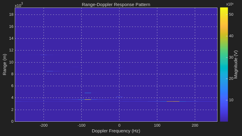
Visualize the received RF data by using the helperVisualizeRadarTargetSimulation helper function. The helper function plots the range-Doppler response and overlays both the 2-D CFAR detection and expected target range-Doppler coordinates.
fig = figure;
ax = axes(fig);
helperVisualizeRadarTargetSimulation(out,sim_in,rdResponse,cfar,0,ax);

Plot Scenario Frames Repeatedly
Simulate all the scenario frames to verify the behavior is as expected. Use the phased.RangeDopplerScope (Phased Array System Toolbox) System object to plot the response in a range-Doppler scope for faster plotting. Alternatively, set the useVerificationScope variable to true to use the same plotting as for the previous verification experiment and save it as a GIF. The GIF shows an example.
useVerificationScope = false; % Verification scope takes longer due to multiple plot layers and cfar detection.
if useVerificationScope
    cStep = 1;
    gifName = "USRPRADARTargetEmulator.gif";
    fig = figure;
    ax = axes(fig);
else
    % Set to "magnitude" units to improve visibility in the plot due to non-existent noise floor in FPGA
    % loopback mode. Set to "db" for log scale when using real RF (device.LoopbackMode="Disabled")
scope = phased.RangeDopplerScope(IQDataInput=false,ResponseUnits="magnitude");
end
restart(scenario);
For the first transmit and receive, set the Background name-value argument to false. The function blocks MATLAB until the current time reaches the start time. Then, in the while loop, set the Background name-value argument to true. The delay elapses in the background while you plot data in MATLAB.
% Schedule next transmission and reception
scheduledTime = getRadioTime(radio)+scheduleTimeOffset;
transmit(device,txPulseTrain,"once",StartTime=scheduledTime);
% Stream samples from the radio front end into the DUT and Capture Antenna
device(captureLength,StartTime=scheduledTime,Background=false);
Assume that each iteration returns the correct number of valid samples and preallocates the array for the helperRadarTargetVisualizeSimulationScope helper function.
out.ValidOut = true(1,captureLength);
Emulate the remaining scenario frames and plot the response in the scope.
while advance(scenario)
    % Retrieve captured samples from the PL DDR Buffer of the capture antenna
    [out.DataOut,nSamps] = capture(device,captureLength);

    % Get the RCS, range, and radial speed for each target
    [targetEnabled,targetRCS,targetRange,targetSpeed] = helperRadarTargetInformation(radarPosition,sim_in.Fc,t1,t2,t3,t4,t5,t6,t7,t8);

    TargetEnabled = sim_in.TargetEnabled ... % Enabled in simulation
    & TargetDelaySamples>0 ... % and delay is greater than zero
    & TargetDelaySamples<sim_in.TargetEmulator_MaxDelayLength;% and delay less than maximum

    maxGainPrev = maxGain;
    maxGain = helperRadarTargetMaxGain(min(targetRange(targetEnabled)),max(planeRcsSignature.Pattern),sim_in.lambda);
    maxGainChange = maxGain/maxGainPrev;
    device.TransmitRadioGain = [device.TransmitRadioGain(1)+pow2db(maxGainChange),device.TransmitRadioGain(2:end)];

    % Call the simulation setup function to adjust target parameters
    sim_in = helperRadarTargetSimulationSetup(targetEnabled,targetRCS,targetRange,targetSpeed,maxGain);
    TargetInc = sim_in.TargetDoppler.*(2^sim_in.TargetEmulator_NCO_accum_wl/sim_in.Fs); % DopFreq to inc
    TargetDelaySamples = abs(sim_in.TargetDelay).*sim_in.Fs - reTxOffset - calibratedFrontEndDelay; % Time to samples

    % Run the simulation
    % Update Registers
    for target = 1:length(TargetEnabled)
        writePort(dut,"e"+string(target),TargetEnabled(target));
        if TargetEnabled(target) % If enabled, write delay, inc and gain
            writePort(dut,"d"+string(target),TargetDelaySamples(target)); % Delay relative to the fixed retransmission offset
            writePort(dut,"i"+string(target),TargetInc(target));
            writePort(dut,"g"+string(target),sim_in.TargetGain(target));
        end
    end

    % Schedule next transmission and reception
    scheduledTime = getRadioTime(radio)+scheduleTimeOffset;
    transmit(device,txPulseTrain,"once",StartTime=scheduledTime);
    % Stream samples from the radio front end into the DUT and Capture Antenna in the background
    device(captureLength,StartTime=scheduledTime,Background=true);

    % % Visualize the output data
    if useVerificationScope
        helperVisualizeRadarTargetSimulation(out,sim_in,rdResponse,cfar,cStep,ax);
        fig.Visible = true;
        drawnow;
        im = frame2im(getframe(fig));
        [A,map] = rgb2ind(im,256);
        if cStep==1
            imwrite(A,map,gifName,"gif",LoopCount=Inf,DelayTime=tUpdate);
        else
            imwrite(A,map,gifName,"gif",WriteMode="append",DelayTime=tUpdate);
        end
        cStep = cStep+1;
    else
helperVisualizeRadarTargetSimulationScope(out,sim_in,rdResponse,scope);
    end
end
Release Hardware Resources
Release the hardware resources.
release(dut);
release(device);