5G NR Downlink CSI Reporting
This example shows how to compute downlink channel state information (CSI) parameters such as the channel quality indicator (CQI), precoding matrix indicator (PMI), and rank indicator (RI), for multiple input multiple output (MIMO) scenarios, as defined in TS 38.214 Section 5.2.2, over a tapped delay line (TDL) channel. The example supports CSI parameter computation for the type I single-panel, type I multi-panel, type II codebooks, and enhanced type II codebooks.
Introduction
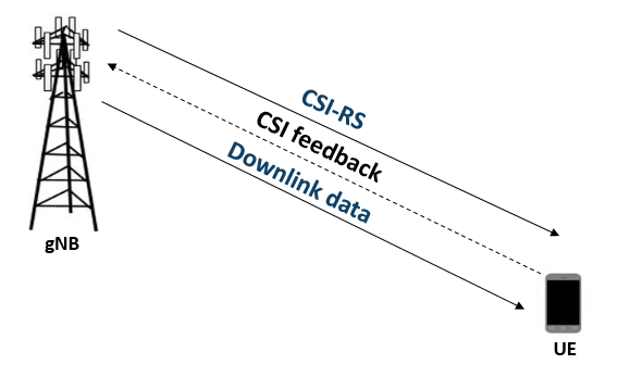
CSI parameters are the quantities related to the state of a channel. The user equipment (UE) reports CSI parameters to the access network node (gNB) as feedback. The CSI feedback includes several parameters, such as the CQI, the PMI, and the RI. The UE uses the channel state information reference signal (CSI-RS) to measure the CSI feedback. Upon receiving the CSI parameters, the gNB schedules downlink data transmissions (such as modulation scheme, code rate, number of transmission layers, and MIMO precoding) accordingly. This figure shows an overview of CSI-RS transmission, CSI computation and feedback, and the transmission of downlink data that is scheduled based on the CSI parameters.
RI Selection
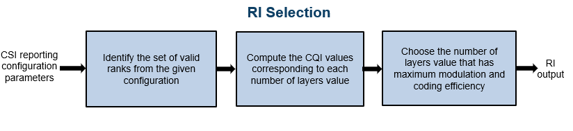
The RI defines the number of possible layers for the downlink transmission under specific channel conditions. The RI also corresponds to the maximum number of uncorrelated paths that the downlink transmission can use. Other CSI parameters like the PMI and CQI are computed based on the rank provided by the RI. For given channel conditions, the hRISelect function computes the CQI values for all valid values of number of transmission layers. The function returns the number of transmission layers that have maximum modulation and coding efficiency.
PMI Selection
The PMI consists of a set of indices corresponding to the precoding matrix. The gNB can apply this precoding matrix for the downlink data transmission. The hDLPMISelect function reports a precoding matrix by considering a codebook from these supported codebooks:
Type I single-panel codebooks, as defined in TS 38.214 Tables 5.2.2.2.1-1 to 5.2.2.2.1-12
Type I multi-panel codebooks, as defined in TS 38.214 Tables 5.2.2.2.2-1 to 5.2.2.2.2-6
Type II codebooks, as defined in TS 38.214 Tables 5.2.2.2.2-1 to 5.2.2.2.3-5
Enhanced type II codebooks, as defined in TS 38.214 Tables 5.2.2.2.5-1 to 5.2.2.2.5-6
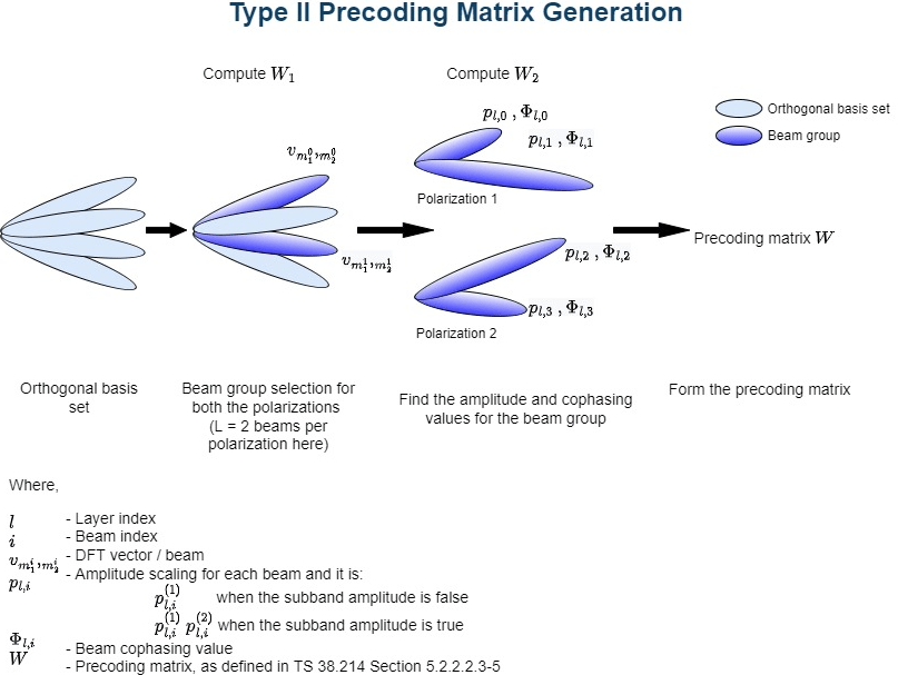
The PMI selection is based on the codebook type, the number of transmission layers, and other CSI reporting configuration parameters such as antenna panel dimensions. Each codebook consists of a set of precoding matrices. NR considers a dual-stage precoding matrix based on the codebooks design from TS 38.214 Sections 5.2.2.2.1 to 5.2.2.2.3 and Section 5.2.2.2.5.
Where,
is a matrix representing a discrete Fourier transform (DFT) beam or beam group for both polarizations based on the codebook type
can be any of the following based on the codebook type:
Beam selection from
Weighting coefficients for the beams in
Cophasing values between two polarizations
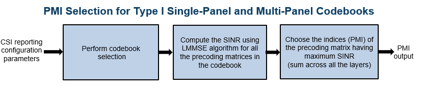
For type I single-panel and multi-panel codebooks, the function computes signal to interference plus noise ratio (SINR) at the receiver side for all precoding matrices from the selected codebook and for the given channel conditions. The function reports the PMI as the set of indices , , as defined in TS 38.214 Section 5.2.2.2.1 for type I single-panel codebooks and TS 38.214 Section 5.2.2.2.2 for type I multi-panel codebooks. These indices correspond to a precoding matrix , which gives the maximum SINR. Type I single and multi-panel codebooks are useful for single-user MIMO scenarios. This figure shows the procedure for PMI selection from type I single-panel and multi-panel codebooks.
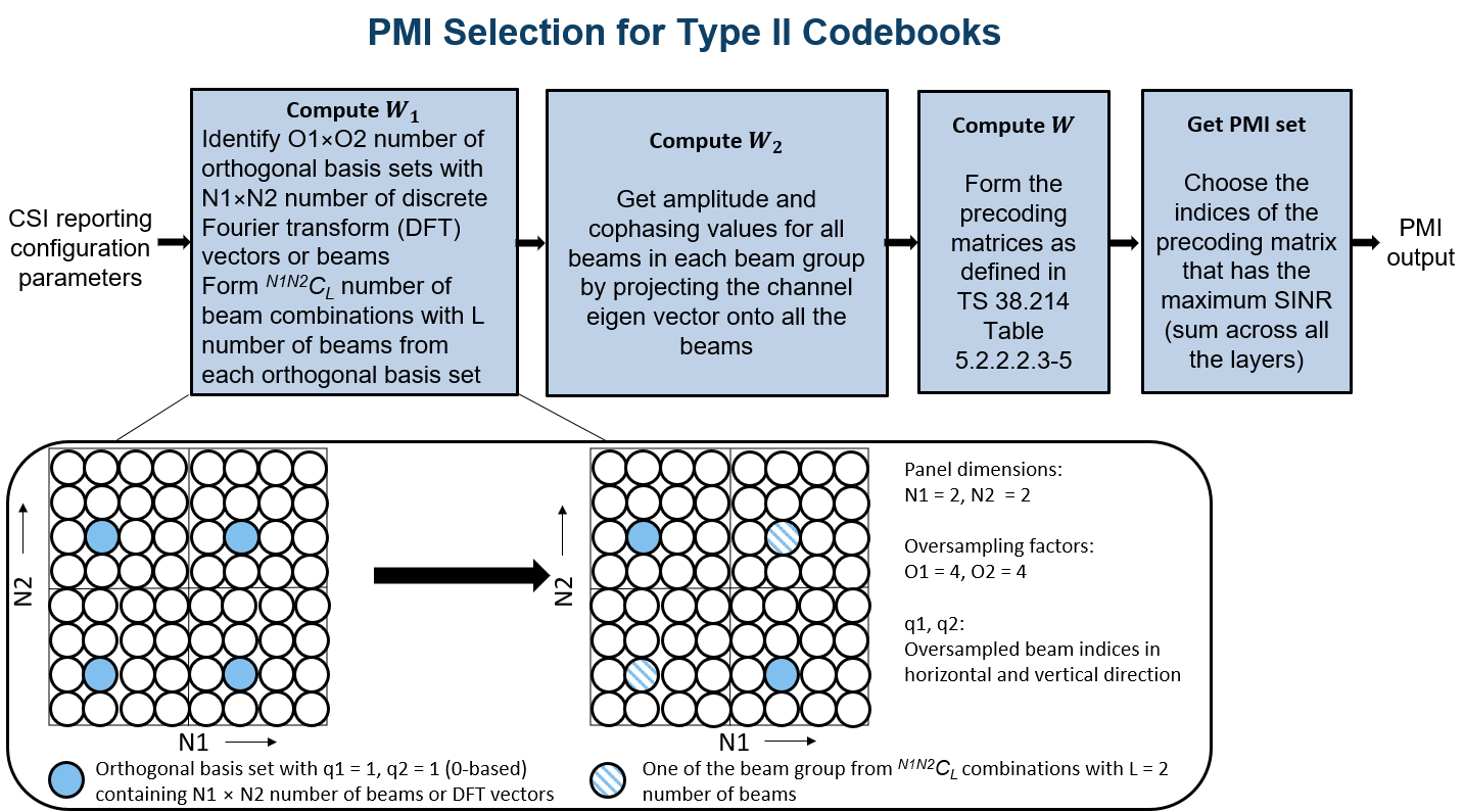
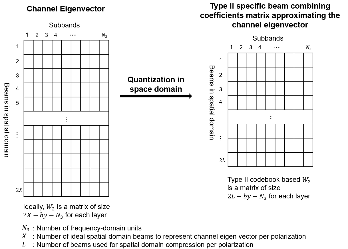
Type II codebooks consider a set of orthogonal DFT beams to form the precoding matrix. As mentioned above, the matrix contains the information related to the DFT beams. For the given channel conditions and the number of DFT beams, the function computes the beam amplitude scaling and cophasing values () for all the DFT beams in each orthogonal beam group so that the linear combination of orthogonal beams approximates the eigenvector of the channel. The function reports the indices and , as defined in TS 38.214 Section 5.2.2.2.3. These indices correspond to the precoding matrix , which gives the maximum SINR. Type II codebook based PMI is more accurate than type I codebook based PMI, as multiple beams are considered in type II codebooks for the approximation of channel eigenvector. Because type II codebooks consider multiple beams, multi-user MIMO scenarios use type II codebooks instead of type I codebooks. These figures show the PMI selection procedure from type II codebooks.
This figure shows the quantization process in space domain (i.e., few beams in the approximation of channel eigenvector) in type II codebooks to form matrix for each layer.
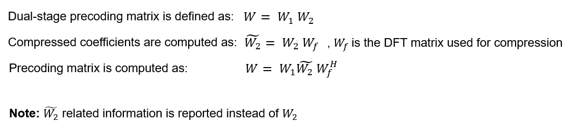
Because type II codebooks support only up to rank 2, the standard introduces enhanced type II codebooks. The PMI computation that is based on enhanced type II codebooks extends type II codebooks by supporting up to rank 4 with one overhead reduction technique. The beam amplitude scaling and cophasing values (also called beam combining coefficients) for all the beams are computed similar to type II codebooks approach. With the rank extension, the feedback overhead increases linearly and with the number of subbands. For this amount of feedback, the uplink resources may not be sufficient. By taking the advantage of the frequency-domain correlation of beam combining coefficients, a process called DFT or frequency-domain compression is employed for enhanced type II codebooks to reduce the feedback overhead.
The figure shows the frequency-domain compression process.
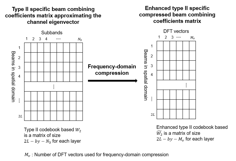
Along with frequency-domain compression, enhanced type II codebooks limit the number of nonzero coefficients in the feedback by ignoring the weaker beam combining coefficients.
CQI Selection
The CQI is an indicator of channel quality. The CQI value is a scalar in the range [0, 15]. The CQI value provides information about the highest modulation scheme and the code rate (MCS) suitable for the downlink transmission to achieve the required block error rate (BLER) for given channel conditions.
The CSI reference resource is a group of downlink frequency-domain and time-domain resources that are configured as defined in TS 38.214 Section 5.2.2.5. The gNB transmits a single physical downlink shared channel (PDSCH) transport block occupying the resource blocks called the CSI reference resource, with a combination of modulation scheme and target code rate that correspond to each CQI index. The UE selects the highest possible CQI, when the PDSCH transport block can be received with a transport block error probability not exceeding:
0.1 when 'cqi-Table' is 'table1' or 'table2'
0.00001 when 'cqi-Table' is 'table3'
The 'cqi-Table' is a higher layer parameter that corresponds to the CQI versus MCS table, and the SINR lookup table is computed for this table. This example uses 'cqi-Table' as 'table1' (TS 38.214 Table 5.2.2.1-2). The relationship between the CQI indices, the modulation scheme, and the code rate (from which the transport block size is derived) is described in TS 38.214 Tables 5.2.2.1-2 to 5.2.2.1-4.
The hCQISelect function computes the CQI value by considering the SINR values that correspond to the reported PMI. This function uses the precalculated lookup table of the CQI index versus , as a reference, if you provide it.
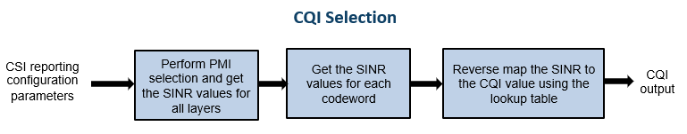
CQI Selection Using SINR Lookup Table
The function maps the SINR values across all layers (corresponding to the reported PMI) to each codeword. For each codeword, the function compares the respective SINR with the values from the table and then selects the CQI value against the maximum SINR, which is less than the codeword SINR. The function sets the CQI value so that the BLER is less than or equal to 0.1 when operated at . If a CQI index of 1 does not satisfy the BLER condition, then the function sets the CQI index to 0. This figure shows the procedure for CQI selection.
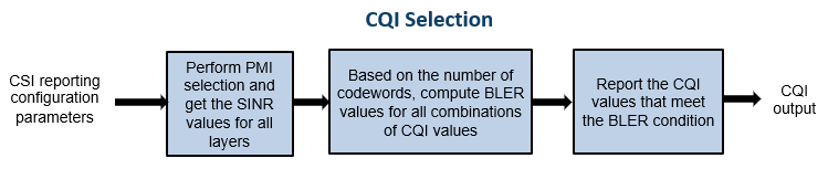
CQI Selection Without SINR Lookup Table
The function computes the CQI values by using the SINR values across all layers corresponding to the reported PMI. Based on the number of codewords, the function forms the combinations of CQI values and reports the one which satisfies the BLER condition.
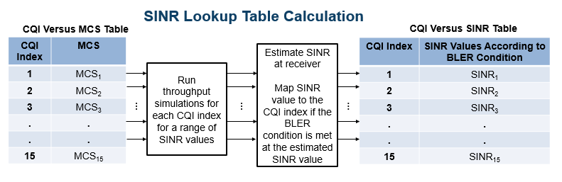
CQI Versus SINR Table
To create the lookup tables, update the NR PDSCH Throughput example by configuring the CSI reference resource, as defined in TS 38.214 Section 5.2.2.5. Perform simulations for PDSCH throughput by specifying the modulation scheme and code rate corresponding to each CQI, the channel conditions, and a finite range of SINR values with zero interference. Map the SINR value observed at the receiver against each CQI index when the target BLER is achieved. This figure shows the procedure for CQI versus SINR table creation.
Outline of Example
This example shows how to compute the CQI and PMI indices for a 4-by-4 MIMO scenario over a TDL channel with the TDL-C delay profile, a delay spread of 300 nanoseconds, and a maximum Doppler shift of 50 Hz. It compares the time-domain and frequency-domain variations of CQI values against the time-domain and frequency-domain variations of SINR values for practical and perfect channel estimation scenarios. The example also highlights the time-domain and frequency-domain variations of the PMI values corresponding to the reported rank for practical and perfect channel estimation scenarios.
Simulation Length and SNR Point
Set the length of the simulation in terms of the number of 10 ms frames. The SNR (SINR with zero interference) is defined per resource element (RE) and applies to each receive antenna. For an explanation of the SNR definition that this example uses, see SNR Definition Used in Link Simulations.
nFrames = 5; % Number of 10 ms frames
SNRdB = 10;  % SNR in dB
Carrier, Bandwidth Part, CSI-RS, and PDSCH DM-RS Configuration
Create a carrier configuration object representing a 10 MHz carrier with a subcarrier spacing of 15 kHz.
carrier = nrCarrierConfig;
carrier.SubcarrierSpacing = 15;
carrier.NSizeGrid = 52;
Configure the size of the bandwidth part (BWP) and the start of the BWP relative to common resource block 0 (CRB 0).
NStartBWP = 0;
NSizeBWP = 52;
Create a CSI-RS configuration object representing a non-zero-power CSI-RS (NZP-CSI-RS) resource set with a set of NZP-CSI-RS resources. Make sure that the NZP-CSI-RS resources have the same code division multiplexing (CDM) types and the same number of CSI-RS ports, as defined in TS 38.214 Section 5.2.2.3.1.
csirs = nrCSIRSConfig;
csirs.CSIRSType = {'nzp','nzp','nzp'};
csirs.RowNumber = [4 4 4];
csirs.NumRB = 52;
csirs.RBOffset = 0;
csirs.CSIRSPeriod = [4 0];
csirs.SymbolLocations = {0, 0, 0};
csirs.SubcarrierLocations = {0, 4, 8};
csirs.Density = {'one','one','one'};
Create a PDSCH demodulation reference signal (DM-RS) configuration as outlined in TS 38.211 Section 7.4.1.1. The UE uses this DM-RS configuration in the definition of the CSI reference resource for CQI calculation.
dmrsConfig = nrPDSCHDMRSConfig; dmrsConfig.DMRSTypeAPosition =2; % Mapping type A only. First DM-RS symbol position (2,3) dmrsConfig.DMRSLength =
2; % Number of front-loaded DM-RS symbols (1(single symbol),2(double symbol)) dmrsConfig.DMRSAdditionalPosition =
1; % Additional DM-RS symbol positions (max range 0...3) dmrsConfig.DMRSConfigurationType =
2; % DM-RS configuration type (1,2) dmrsConfig.NumCDMGroupsWithoutData =
3; % CDM groups without data (1,2,3)
Configure the number of transmit and receive antennas. The number of transmit antennas must be equal to the number of CSI-RS ports because this example does not consider the mapping of antenna ports to physical antennas.
nTxAnts = csirs.NumCSIRSPorts(1);
nRxAnts = 4;
Validate the CSI-RS configuration object.
validateCSIRSConfig(carrier,csirs,nTxAnts);
CSI Reporting Configuration
Specify the parameters for the CQI, PMI, and RI computation as a structure with these fields:
NSizeBWP— Size of the BWP in terms of the number of physical resource blocks (PRBs)NStartBWP— Starting PRB index of the BWP relative to CRB 0CQITable— Channel quality indicator table ('table1','table2','table3'), as defined in TS 38.214 Tables 5.2.2.1-2 to 5.2.2.1-4CodebookType— Codebook type for CSI parameter computation ('Type1SinglePanel','Type1MultiPanel','Type2','eType2')PanelDimensions— Antenna panel dimensions corresponding to theCodebookTypefield
If CodebookType is set to any one of ('Type1SinglePanel', 'Type2', 'eType2'), the panel dimensions are in the form of [N1 N2] according to TS 38.214 Table 5.2.2.2.1-2. This figure shows the supported panel dimensions.


If CodebookType is set to 'Type1MultiPanel', the panel dimensions are in the form of [Ng N1 N2] according to TS 38.214 Table 5.2.2.2.2-1. This figure shows the supported type I multi-panel dimensions.


CQIMode— Mode of CQI reporting ('Subband','Wideband')PMIMode— Mode of PMI reporting ('Subband','Wideband')SubbandSize— Size of the subband, as defined in TS 38.214 Table 5.2.1.4-2 (required only whenCQIModeorPMIModeis'Subband')PRGSize— Precoding resource block group (PRG) size for the CQI calculation (required only when the reporting must be done for the report quantity 'cri-RI-i1-CQI' andCodebookTypeis configured as'Type1SinglePanel', as defined in TS 38.214 Section 5.2.1.4.2)CodebookMode— Codebook mode according to which the codebooks are derived. The value must be 1 or 2. This field is applicable only when theCodebookTypeis specified as'Type1SinglePanel'or'Type1MultiplePanel'. When theCodebookTypeis specified as'Type1SinglePanel', this field is required only when the number of transmission layers is 1 or 2 and the number of CSI-RS ports is greater than 2. When theCodebookTypeis specified as'Type1MultiplePanel', this field is required for all the number of transmission layers, but theCodebookModevalue 2 is applicable only for the panel configurations with Ng value 2.CodebookSubsetRestriction— For type I single-panel and multi-panel codebooks, it is a restriction parameter pertaining to the codebook index set , that is, or restriction parameter, as defined in TS 38.214 Section 5.2.2.2.1. This field denotes the set of indices ([, ]) that are restricted from the consideration for the PMI computation. For type II codebooks, this field restricts the maximum amplitudes that are allowed for four vector groups indicated by for , as defined in TS 38.214 Section 5.2.2.2.3. For enhanced type II codebooks, this field restricts the maximum average amplitude coefficients that are allowed for four vector groups indicated by for , as defined in TS 38.214 Section 5.2.2.2.5. In any of the codebook types, this field is specified as a bitmap.i2Restriction— Restriction parameter pertaining to the codebook index . This field denotes the set of indices that are restricted from the consideration for the PMI computation. This field is applicable only whenCodebookTypeis'Type1SinglePanel'.RIRestriction— Restriction parameter pertaining to the rank indicator, which implies the set of ranks that are restricted from usage for the RI computation.NumberOfBeams— Number of beams in the beam group per polarization. This field is applicable only when theCodebookTypeis specified as'Type2'. The value must be one of {2, 3, 4}.PhaseAlphabetSize— Represents the Range of the phases that are considered for the computation of indices. This field is applicable only when theCodebookTypeis specified as'Type2'. The value must be one of {4, 8}. The value 4 represents the phases corresponding to QPSK and the value 8 represents the phases corresponding to 8-PSK.SubbandAmplitude— Logical scalar that enables the reporting of differential amplitudes per subband when set totrueand disables differential subband amplitude in PMI reporting when set tofalse. The value must be one of {true,false}. This field is applicable whenCodebookTypeis specified as'Type2'andPMIModeis'Subband'.ParameterCombination— It is a positive scalar integer in the range 1...8. This is applicable whenCodebookTypeis specified as'eType2'. This parameter defines the number of beams and two other parameters as defined in TS 38.214 Table 5.2.2.2.5-1.NumberOfPMISubbandsPerCQISubband— Represents the number of PMI subbands within one CQI subband, as defined in TS 38.214 Section 5.2.2.2.5. It is a positive scalar integer, and it must be either 1 or 2.
Configure CSI reporting configuration parameters.
reportConfig.NStartBWP = NStartBWP;
reportConfig.NSizeBWP = NSizeBWP;
reportConfig.CQITable = 'table1';
reportConfig.CodebookType = 'Type1SinglePanel';
reportConfig.PanelDimensions = [2 1];
reportConfig.CQIMode = 'Subband';
reportConfig.PMIMode = 'Subband';
reportConfig.SubbandSize = 4;
reportConfig.PRGSize = [];
reportConfig.CodebookMode = 1;
reportConfig.CodebookSubsetRestriction = [];
reportConfig.i2Restriction = [];
reportConfig.RIRestriction = [];
reportConfig.NumberOfBeams = 2;                    % Applicable only when CodebookType is 'Type2'
reportConfig.SubbandAmplitude = false;             % Applicable only when CodebookType is 'Type2'
reportConfig.PhaseAlphabetSize = 4;                % Applicable only when CodebookType is 'Type2'
reportConfig.ParameterCombination = 2;             % Applicable only when CodebookType is 'eType2'
reportConfig.NumberOfPMISubbandsPerCQISubband = 2; % Applicable only when CodebookType is 'eType2'

% Adjust the RIRestriction according to the provided DM-RS
% configuration. If the number of DM-RS antenna ports in a given
% configuration is less than the possible number of ranks for a CSI
% report, restrict those ranks through CSIReportConfig
reportConfig.RIRestriction = updateRankRestriction(dmrsConfig,reportConfig);
Propagation Channel Model Configuration
Create a TDL channel with the TDL-C delay profile, a delay spread of 300 nanoseconds, and a maximum Doppler shift of 50 Hz.
channel = nrTDLChannel;
channel.NumTransmitAntennas = nTxAnts;
channel.NumReceiveAntennas = nRxAnts;
channel.DelayProfile = 'TDL-C';
channel.MaximumDopplerShift = 50;
channel.DelaySpread = 300e-9;
Set the sampling rate for the channel model by using the value that the nrOFDMInfo function returns.
waveformInfo = nrOFDMInfo(carrier);
channel.SampleRate = waveformInfo.SampleRate;
Get the maximum number of delayed samples by a channel multipath component. The maximum number of delayed samples is calculated from the channel path with the largest delay and the implementation delay of the channel filter. The number of samples that correspond to the maximum channel delay is required later to flush the channel filter to obtain the received signal.
chInfo = info(channel);
maxChDelay = chInfo.MaximumChannelDelay;
Processing Loop
For each slot, generate the CSI-RS, transmit it through the channel, and then process at the receiver side to compute the CQI, PMI, and RI values. Follow the steps for the transmit-to-receive processing for each slot.
Generate the resource grid — Generate the slot grid that contains the CSI-RS and map the slot grid from CSI-RS ports to transmit antennas.
Generate the waveform — Perform orthogonal frequency division multiplexing (OFDM) modulation on the generated grid by using the
nrOFDMModulatefunction.Model and apply a noisy channel — Pass the waveform through a TDL-C fading channel, and then add the additive white Gaussian noise (AWGN). The SNR is defined per RE and applies to each receive antenna.
Perform timing synchronization and OFDM demodulation — For practical synchronization, correlate the received waveform with the CSI-RS. For perfect synchronization, use the path gains and path filters of the channel. Perform OFDM demodulation on the synchronized signal using the
nrOFDMDemodulatefunction.Perform channel estimation — For practical channel estimation, use the CSI-RS. For perfect channel estimation, use the path gains, the path filters, and the sample times of channel snapshots.
Compute CQI, PMI, and RI values — Compute CQI, PMI, and RI values using practical and perfect channel estimations.
Calculate total number of slots.
totSlots = nFrames*carrier.SlotsPerFrame;
Initialize variables to store CQI, PMI, RI, and subband SINR values for practical and perfect channel estimation scenarios.
After the completion of processing loop:
The variables
cqiPracticalPerSlot,cqiPerfectPerSlot,SINRPerSubbandPerCWPractical, andSINRPerSubbandPerCWPrerfectare multidimensional arrays of sizenumSBs-by-2-by-totSlots. ThenumSBsvalue is equal to the number of subbands plus 1, that is, the corresponding wideband value followed by subband values. The second dimension value denotes the maximum possible number of codewords.The variables
pmiPracticalPerSlotandpmiPerfectPerSlotare arrays of structures of sizetotSlots. The structure represents the PMI values with fieldsi1andi2.The variables
riPracticalPerSlotandriPerfectPerSlotare arrays of size 1-by-totSlots.
cqiPracticalPerSlot = [];
subbandCQIPractical = [];
pmiPracticalPerSlot = struct('i1',[],'i2',[]);
SINRPerSubbandPerCWPractical = [];
cqiPerfectPerSlot = [];
subbandCQIPerfect = [];
pmiPerfectPerSlot = struct('i1',[],'i2',[]);
SINRPerSubbandPerCWPerfect = [];
riPracticalPerSlot = [];
riPerfectPerSlot = [];

% Get number of CSI-RS ports
csirsPorts = csirs.NumCSIRSPorts(1);

% Get CDM lengths corresponding to configured CSI-RS resources
cdmLengths = getCDMLengths(csirs);

% Initialize the practical timing offset as zero. It is updated in the
% slots when the correlation is strong for practical synchronization.
offsetPractical = 0;

% Initialize a variable to store the information of the slots
% where NZP-CSI-RS resources are present. It is of length totSlots.
totSlotsBinaryVec = zeros(1,totSlots);

% Set RNG state for repeatability
rng('default');

% Loop over all slots
for nslot = 0:totSlots - 1
    % Create carrier resource grid for one slot
    csirsSlotGrid = nrResourceGrid(carrier,csirsPorts);

    % Update slot number in carrier configuration object
    carrier.NSlot = nslot;

    % Generate CSI-RS indices and symbols
    csirsInd = nrCSIRSIndices(carrier,csirs);
    csirsSym = nrCSIRS(carrier,csirs);

    % Map CSI-RS to slot grid
    csirsSlotGrid(csirsInd) = csirsSym;

    % Map CSI-RS ports to transmit antennas
    wtx = eye(csirsPorts,nTxAnts);
    txGrid = reshape(reshape(csirsSlotGrid,[],csirsPorts)*wtx,size(csirsSlotGrid,1),size(csirsSlotGrid,2),nTxAnts);

    % Perform OFDM modulation to generate time-domain waveform
    txWaveform = nrOFDMModulate(carrier,txGrid);

    % Append zeros at the end of the transmitted waveform to flush channel
    % content. These zeros take into account any delay introduced in the
    % channel. The channel delay is a mix of multipath delay and
    % implementation delay. This value may change depending on the sampling
    % rate, delay profile, and delay spread.
    txWaveform = [txWaveform; zeros(maxChDelay,size(txWaveform,2))]; %#ok<AGROW>

    % Transmit waveform through channel
    [rxWaveform,pathGains,sampleTimes] = channel(txWaveform);

    % Generate and add AWGN to received waveform
    SNR = 10^(SNRdB/10);                                                % Linear SNR value
    sigma = 1/(sqrt(2.0*nRxAnts*double(waveformInfo.Nfft)*SNR));        % Noise standard deviation
    noise = sigma*complex(randn(size(rxWaveform)),randn(size(rxWaveform)));
    rxWaveform = rxWaveform + noise;

    % Perform practical timing estimation. Correlate the received waveform
    % with the CSI-RS to obtain the timing offset estimate and the
    % correlation magnitude. Use the hSkipWeakTimingOffset function to
    % update the receiver timing offset. If the correlation peak is weak,
    % the current timing estimate is ignored and the previous offset is
    % used.
    [t,mag] = nrTimingEstimate(carrier,rxWaveform,csirsInd,csirsSym);
    offsetPractical = hSkipWeakTimingOffset(offsetPractical,t,mag);

    % Get path filters
    pathFilters = getPathFilters(channel);
    % Perform perfect timing estimation
    offsetPerfect = nrPerfectTimingEstimate(pathGains,pathFilters);

    % Perform time-domain offset correction for practical and
    % perfect timing estimation scenarios
    rxWaveformPractical = rxWaveform(1+offsetPractical:end,:);
    rxWaveformPerfect = rxWaveform(1+offsetPerfect:end,:);

    % Perform OFDM demodulation on previously synchronized waveforms
    rxGridPractical = nrOFDMDemodulate(carrier,rxWaveformPractical);
    rxGridPerfect = nrOFDMDemodulate(carrier,rxWaveformPerfect);

    % Append zeros when the timing synchronization results in an incomplete
    % slot
    symbPerSlot = carrier.SymbolsPerSlot;
    K = size(rxGridPractical,1);
    LPractical = size(rxGridPractical,2);
    LPerfect = size(rxGridPerfect,2);
    if LPractical < symbPerSlot
        rxGridPractical = cat(2,rxGridPractical,zeros(K,symbPerSlot-LPractical,nRxAnts));
    end
    if LPerfect < symbPerSlot
        rxGridPerfect = cat(2,rxGridPerfect,zeros(K,symbPerSlot-LPerfect,nRxAnts));
    end
    rxGridPractical = rxGridPractical(:,1:symbPerSlot,:);
    rxGridPerfect = rxGridPerfect(:,1:symbPerSlot,:);

    % Consider only the NZP-CSI-RS symbols and indices for channel estimation
    nzpCSIRSSym = csirsSym(csirsSym ~= 0);
    nzpCSIRSInd = csirsInd(csirsSym ~= 0);

    % Calculate practical channel estimate. Use a time-averaging window
    % that covers all the transmitted CSI-RS symbols.
    [PracticalHest,nVarPractical] = nrChannelEstimate(carrier,rxGridPractical, ...
        nzpCSIRSInd,nzpCSIRSSym,'CDMLengths',cdmLengths,'AveragingWindow',[0 5]);

    % Perform perfect channel estimation
    PerfectHest = nrPerfectChannelEstimate(carrier,pathGains,pathFilters,offsetPerfect,sampleTimes);

    % Get perfect noise estimate value from noise realization
    noiseGrid = nrOFDMDemodulate(carrier,noise(1+offsetPerfect:end,:));
    nVarPerfect = var(noiseGrid(:));
    if ~isempty(nzpCSIRSInd)
        % Set the totSlotsBinaryVec value corresponding to the slot
        % index where NZP-CSI-RS is present to 1
        totSlotsBinaryVec(nslot+1) = 1;

        % Calculate the RI value using practical channel estimate
        numLayersPractical = hRISelect(carrier,csirs,dmrsConfig,reportConfig,PracticalHest,nVarPractical,'MaxSE');

        % Calculate CQI and PMI values using practical channel estimate
        [cqiPractical,pmiPractical,cqiInfoPractical,pmiInfoPractical] = hCQISelect(carrier,csirs,dmrsConfig, ...
            reportConfig,numLayersPractical,PracticalHest,nVarPractical);
        numCodeWordsPr = size(cqiPractical,2);
        numSBs = size(cqiPractical,1);

        % Store CQI, PMI, RI, and subband SINR values of each slot for the
        % practical channel estimation scenario. Because the number of
        % codewords can vary based on the rank, append NaNs to the
        % CQI-related variables to account for the second codeword
        % information in the slots where only one codeword is present.
        riPracticalPerSlot(1,nslot+1) = numLayersPractical; %#ok<SAGROW>
        cqiPracticalPerSlot(:,:,nslot+1) = [cqiPractical NaN(numSBs,2-numCodeWordsPr)]; %#ok<SAGROW>
        pmiPracticalPerSlot(nslot+1) = pmiPractical;
        subbandCQIPractical(:,:,nslot+1) = [cqiInfoPractical.SubbandCQI NaN(numSBs,2-numCodeWordsPr)]; %#ok<SAGROW>
        SINRPerSubbandPerCWPractical(:,:,nslot+1) = [cqiInfoPractical.SINRPerSubbandPerCW NaN(numSBs,2-numCodeWordsPr)]; %#ok<SAGROW>

        % Calculate the RI value using perfect channel estimate
        numLayersPerfect = hRISelect(carrier,csirs,dmrsConfig,reportConfig,PerfectHest,nVarPerfect,'MaxSE');

        % Calculate CQI and PMI values using perfect channel estimate
        [cqiPerfect,pmiPerfect,cqiInfoPerfect,pmiInfoPerfect] = hCQISelect(carrier,csirs,dmrsConfig, ...
            reportConfig,numLayersPerfect,PerfectHest,nVarPerfect);
        numCodeWordsPe = size(cqiPerfect,2);

        % Store CQI, PMI, RI, and subband SINR values of each slot for the
        % perfect channel estimation scenario. Because the number of
        % codewords can vary based on the rank, append NaNs to the
        % CQI-related variables to account for the second codeword
        % information in the slots where only one codeword is present.
        riPerfectPerSlot(1,nslot+1) = numLayersPerfect; %#ok<SAGROW>
        cqiPerfectPerSlot(:,:,nslot+1) = [cqiPerfect NaN(numSBs,2-numCodeWordsPe)]; %#ok<SAGROW>
        subbandCQIPerfect(:,:,nslot+1) = [cqiInfoPerfect.SubbandCQI NaN(numSBs,2-numCodeWordsPe)]; %#ok<SAGROW>
        pmiPerfectPerSlot(nslot+1) = pmiPerfect;
        SINRPerSubbandPerCWPerfect(:,:,nslot+1) = [cqiInfoPerfect.SINRPerSubbandPerCW NaN(numSBs,2-numCodeWordsPe)]; %#ok<SAGROW>
    end
end

% Get the active slot numbers (1-based) in which NZP-CSI-RS is present
activeSlotNum = find(totSlotsBinaryVec);

% Fill the CQI, PMI and RI variables with NaNs in the slots where NZP-CSI-RS is
% absent according to codebook type
[cqiPracticalPerSlot,subbandCQIPractical,pmiPracticalPerSlot,SINRPerSubbandPerCWPractical, ...
    cqiPerfectPerSlot,subbandCQIPerfect,pmiPerfectPerSlot,SINRPerSubbandPerCWPerfect,riPracticalPerSlot, ...
    riPerfectPerSlot] = fillInactiveSlots(cqiPracticalPerSlot,subbandCQIPractical, ...
    pmiPracticalPerSlot,SINRPerSubbandPerCWPractical,cqiPerfectPerSlot,subbandCQIPerfect,pmiPerfectPerSlot, ...
    SINRPerSubbandPerCWPerfect,riPracticalPerSlot,riPerfectPerSlot,reportConfig,totSlotsBinaryVec,activeSlotNum);
Compare CQI, PMI, and RI Values Reported in Practical and Perfect Channel Estimation Scenarios
Plot CQI Indices
Plot the wideband SINR values and wideband CQI values for each codeword for practical and perfect channel estimation scenarios. The plot shows only the slots in which the CSI-RS is transmitted or in which the CQI is calculated. The figure shows how the SINR and the corresponding reported CQI vary across the slots due to channel fading.
plotWidebandCQIAndSINR(cqiPracticalPerSlot,cqiPerfectPerSlot, ...
    SINRPerSubbandPerCWPractical,SINRPerSubbandPerCWPerfect,activeSlotNum);
Plot the subband SINR values and subband CQI values for each codeword for practical and perfect channel estimation scenarios. The plot shows the variations of SINR and CQI values across the subbands for a specified slot number (0-based) if the CQI is reported in that slot. Otherwise, plot is not generated because the CQI is not reported.
The plotSubbandCQIAndSINR function plots the CQI values across all subbands only when CQIMode is configured as 'Subband'.
% Provide slot number for which subband CQI values and PMI i2 indices must be plotted
slotNumForSBType1 = 0; % Consider slot number as 0 (0-based) here, because CSI is
                       % reported in that slot for the configured CSI-RS resource(s)
plotSubbandCQIAndSINR(subbandCQIPractical,subbandCQIPerfect, ...
    SINRPerSubbandPerCWPractical,SINRPerSubbandPerCWPerfect,activeSlotNum,slotNumForSBType1);

Plot PMI and RI Indices
First plot in this section shows the variations of RI indices due to channel fading conditions, for practical and perfect channel estimation scenarios. The plot shows only the slots in which the CSI-RS is transmitted or in which RI is calculated.
Codebook Type 'Type1SinglePanel'
The below code shows the variations of PMI due to channel fading conditions, for practical and perfect channel estimation scenarios.
The PMI indices are and , as defined in TS 38.214 Section 5.2.2.2.1.
The first plot shows the rank and the corresponding PMI indices variation across multiple slots.
The second plot shows the variation in indices across the:
Slots when the
PMIModeis specified as'Wideband'Subbands in the specified slot when the
PMIModeis specified as'Subband'
Codebook Type 'Type1MultiPanel'
The below code shows the variations of PMI due to channel fading conditions, for practical and perfect channel estimation scenarios.
The PMI indices are and , as defined in TS 38.214 Section 5.2.2.2.2.
In this case, the first two plots show the rank and the corresponding PMI indices ( to ) variation across the slots.
The third plot shows the variation in each of the indices ( to ) across the:
Slots when the
PMIModeis specified as'Wideband'Subbands in the specified slot when the
PMIModeis specified as'Subband'
Codebook Type 'Type2' or 'eType2'
The below code shows the grid of beams by highlighting the DFT vectors or beams that are used to construct the precoding matrix, for practical and perfect channel estimation scenarios. The plot shows the type II or enhanced type II PMI related information for a specified slot number (0-based), if PMI is reported in that slot. Otherwise, plot is not generated because the PMI is not reported.
For type II codebooks, the PMI indices are defined in TS 38.214 Section 5.2.2.2.3. These indices are:
and for single layer and
SubbandAmplitudeas'false'and for single layer and
SubbandAmplitudeas'true'and for two layers and
SubbandAmplitudeas'false'and for two layers and
SubbandAmplitudeas'true'
For enhanced type II codebooks, the PMI indices are defined in TS 38.214 Section 5.2.2.2.5. These indices are:
and for single layer
and for two layers
and for three layers
and for four layers
The first plot shows the rank variations, and second plot shows the grid of beams for practical and perfect channel estimation scenarios.
% To see the PMI and RI plots for the type I single or multi-panel
% codebooks, set the showType1PMIandRIPlots flag to true
showType1PMIandRIPlots = true;
% To see the PMI and RI plots for the type II codebooks, set the
% showType2PMI flag to true
showType2PMIRI = true;
if (strcmpi(reportConfig.CodebookType,'Type1SinglePanel') || strcmpi(reportConfig.CodebookType,'Type1MultiPanel')) && showType1PMIandRIPlots
    plotType1PMIAndRI(pmiPracticalPerSlot,pmiPerfectPerSlot,riPracticalPerSlot, ...
        riPerfectPerSlot,activeSlotNum,slotNumForSBType1);
elseif (strcmpi(reportConfig.CodebookType,'Type2') || strcmpi(reportConfig.CodebookType,'eType2')) && showType2PMIRI
    slotNumForType2PMI = 0; % 0-based
    plotType2PMIAndRI(pmiPracticalPerSlot,pmiPerfectPerSlot,riPracticalPerSlot, ...
        riPerfectPerSlot,reportConfig.PanelDimensions,reportConfig.NumberOfBeams,activeSlotNum,slotNumForType2PMI);
end


Summary and Further Exploration
This example shows how to compute downlink CSI parameters such as the CQI and PMI from type I single-panel codebooks and RI for a MIMO scenario with a TDL channel. The example also supports the computation of CSI parameters using type I multi-panel, type II, and enhanced type II codebooks.
You can modify carrier, channel, CSI-RS resource configurations, and CSI reporting configuration parameters (such as the codebook type, the mode of CQI and PMI reporting, and the subband size) and observe the variations in the computed CQI, PMI, and RI values across time (slots) and frequency (subbands).
References
[1] 3GPP TS 38.214. "NR; Physical layer procedures for data." 3rd Generation Partnership Project; Technical Specification Group Radio Access Network.
Local Functions
This example uses these local functions to validate the CSI-RS configuration object and to plot the computed CQI, PMI, and RI values.
function validateCSIRSConfig(carrier,csirs,nTxAnts)
%   Validates the CSI-RS configuration, given the carrier specific
%   configuration object, CSI-RS configuration object, and the number of
%   transmit antennas.

    % Validate the number of CSI-RS ports
    if ~isscalar(unique(csirs.NumCSIRSPorts))
        error('nr5g:InvalidCSIRSPorts', ...
            'All the CSI-RS resources must be configured to have the same number of CSI-RS ports.');
    end

    % Validate the CDM lengths
    if ~iscell(csirs.CDMType)
        cdmType = {csirs.CDMType};
    else
        cdmType = csirs.CDMType;
    end
    if (~all(strcmpi(cdmType,cdmType{1})))
        error('nr5g:InvalidCSIRSCDMTypes', ...
            'All the CSI-RS resources must be configured to have the same CDM lengths.');
    end
    if nTxAnts ~= csirs.NumCSIRSPorts(1)
        error('nr5g:InvalidNumTxAnts',['Number of transmit antennas (' num2str(nTxAnts) ...
            ') must be equal to the number of CSI-RS ports (' num2str(csirs.NumCSIRSPorts(1)) ').']);
    end

    % Check for the overlap between the CSI-RS indices
    csirsInd = nrCSIRSIndices(carrier,csirs,"OutputResourceFormat",'cell');
    numRes = numel(csirsInd);
    csirsIndAll = cell(1,numRes);
    ratioVal = csirs.NumCSIRSPorts(1)/prod(getCDMLengths(csirs));
    for resIdx = 1:numRes
        if ~isempty(csirsInd{resIdx})
            grid = nrResourceGrid(carrier,csirs.NumCSIRSPorts(1));
            [~,tempInd] = nrExtractResources(csirsInd{resIdx},grid);
            if numel(tempInd)/numel(csirsInd{resIdx}) ~= ratioVal
                error('nr5g:OverlappedCSIRSREsSingleResource',['CSI-RS indices of resource ' ...
                    num2str(resIdx) ' must be unique. Try changing the symbol or subcarrier locations.']);
            end
            csirsIndAll{resIdx} = tempInd(:);
            for idx = 1:resIdx-1
                overlappedInd = ismember(csirsIndAll{idx},csirsIndAll{resIdx});
                if any(overlappedInd)
                    error('nr5g:OverlappedCSIRSREsMultipleResources',['The resource elements of the ' ...
                        'configured CSI-RS resources must not overlap. Try changing the symbol or ' ...
                        'subcarrier locations of CSI-RS resource ' num2str(idx) ' and resource ' num2str(resIdx) '.']);
                end
            end
        end
    end
end

function cdmLengths = getCDMLengths(csirs)
%   Returns the CDM lengths, given the CSI-RS configuration object.

    CDMType = csirs.CDMType;
    if ~iscell(csirs.CDMType)
        CDMType = {csirs.CDMType};
    end
    CDMTypeOpts = {'noCDM','fd-CDM2','CDM4','CDM8'};
    CDMLengthOpts = {[1 1],[2 1],[2 2],[2 4]};
    cdmLengths = CDMLengthOpts{strcmpi(CDMTypeOpts,CDMType{1})};
end

function [cqiPracticalPerSlot,subbandCQIPractical,pmiPracticalPerSlot,SINRPerSubbandPerCWPractical,cqiPerfectPerSlot, ...
    subbandCQIPerfect,pmiPerfectPerSlot,SINRPerSubbandPerCWPerfect,riPracticalPerSlot,riPerfectPerSlot] = fillInactiveSlots(cqiPracticalPerSlot, ...
    subbandCQIPractical,pmiPracticalPerSlot,SINRPerSubbandPerCWPractical,cqiPerfectPerSlot,subbandCQIPerfect,pmiPerfectPerSlot, ...
    SINRPerSubbandPerCWPerfect,riPracticalPerSlot,riPerfectPerSlot,reportConfig,totSlotsBinaryVec,activeSlots)
%   Returns the CQI, PMI, and RI related variables filled with NaNs in the
%   slots where NZP-CSI-RS is not present according to the codebook type from
%   the report configuration structure. Note that the CQI, PMI, and RI
%   variables are returned as empty if there are no NZP-CSI-RS resources,
%   that is, no active slots in the entire simulation duration.

    % Compute the indices of the slots and the number of slots in which
    % NZP-CSI-RS is not present
    inactiveSlotIdx = ~totSlotsBinaryVec;
    numInactiveSlots = nnz(inactiveSlotIdx);

    if ~isempty(activeSlots)
        numCQISBs = size(cqiPracticalPerSlot,1);

        % Get the codebook type
        codebookType = 'Type1SinglePanel';
        if isfield(reportConfig,'CodebookType')
            codebookType = validatestring(reportConfig.CodebookType,{'Type1SinglePanel','Type1MultiPanel','Type2','eType2'},'fillInactiveSlots','CodebookType field');
        end

        % Fill the CQI, PMI, and RI variables with NaNs in the slots where NZP-CSI-RS is
        % not present
        cqiPracticalPerSlot(:,:,inactiveSlotIdx) = NaN(numCQISBs,2,numInactiveSlots);
        subbandCQIPractical(:,:,inactiveSlotIdx) = NaN(numCQISBs,2,numInactiveSlots);
        SINRPerSubbandPerCWPractical(:,:,inactiveSlotIdx) = NaN(numCQISBs,2,numInactiveSlots);
        cqiPerfectPerSlot(:,:,inactiveSlotIdx) = NaN(numCQISBs,2,numInactiveSlots);
        subbandCQIPerfect(:,:,inactiveSlotIdx) = NaN(numCQISBs,2,numInactiveSlots);
        SINRPerSubbandPerCWPerfect(:,:,inactiveSlotIdx) = NaN(numCQISBs,2,numInactiveSlots);
        riPracticalPerSlot(inactiveSlotIdx) = NaN;
        riPerfectPerSlot(inactiveSlotIdx) = NaN;

        numi1Indices = 3;
        numi2Indices = 1;
        if strcmpi(codebookType,'Type1MultiPanel')
            numi1Indices = 6;
            numi2Indices = 3;
        end
        numPMISBs = size(pmiPerfectPerSlot(activeSlots(1)).i2,2);
        [pmiPerfectPerSlot(inactiveSlotIdx),pmiPracticalPerSlot(inactiveSlotIdx)] = deal(struct('i1',NaN(1,numi1Indices),'i2',NaN(numi2Indices,numPMISBs)));
    end
end

function RIRestriction = updateRankRestriction(dmrsConfig,CSIReportConfig)
% Adjust the CSI report configuration to limit the possible ranks for the given DMRS configuration
    RIRestriction    =  CSIReportConfig.RIRestriction;

    if ~dmrsConfig.DMRSEnhancedR18 && (dmrsConfig.DMRSLength == 1) && strcmpi(CSIReportConfig.CodebookType, 'Type1SinglePanel')
        if (dmrsConfig.DMRSConfigurationType == 1)
            % Allow ranks up to four for DMRS configuration type 1
            dmrsAllowedRanks    = [ones(1,4) zeros(1,4)];
        else
            % Allow ranks up to six for DMRS configuration type 2
            dmrsAllowedRanks    = [ones(1,6) zeros(1,2)];
        end

        RIRestriction = RIRestriction.*dmrsAllowedRanks;
    end
end

function plotWidebandCQIAndSINR(cqiPracticalPerSlot,cqiPerfectPerSlot,SINRPerSubbandPerCWPractical,SINRPerSubbandPerCWPerfect,activeSlotNum)
%   Plots the wideband SINR and wideband CQI values for each codeword
%   across all specified active slots (1-based) (in which the CQI is
%   reported as other than NaN) for practical and perfect channel
%   estimation cases.

    % Check if there are no slots in which NZP-CSI-RS is present
    if isempty(activeSlotNum)
        disp('No CQI data to plot, because there are no slots in which NZP-CSI-RS is present.');
        return;
    end
    cqiPracticalPerCW = permute(cqiPracticalPerSlot(1,:,:),[1 3 2]);
    cqiPerfectPerCW = permute(cqiPerfectPerSlot(1,:,:),[1 3 2]);
    SINRPerCWPractical = permute(SINRPerSubbandPerCWPractical(1,:,:),[1 3 2]);
    SINRPerCWPerfect = permute(SINRPerSubbandPerCWPerfect(1,:,:),[1 3 2]);

    % Extract wideband CQI indices for slots where NZP-CSI-RS is present
    cqiPracticalPerCWActiveSlots = cqiPracticalPerCW(1,activeSlotNum,:);
    cqiPerfectPerCWActiveSlots = cqiPerfectPerCW(1,activeSlotNum,:);
    widebandSINRPractical = 10*log10(SINRPerCWPractical(1,activeSlotNum,:));
    widebandSINRPerfect = 10*log10(SINRPerCWPerfect(1,activeSlotNum,:));

    if isempty(reshape(cqiPracticalPerCWActiveSlots(:,:,1),1,[]))
        disp('No CQI data to plot, because all CQI values are NaNs.');
        return;
    end

    figure();
    plotWBCQISINR(widebandSINRPerfect,widebandSINRPractical,211,activeSlotNum,'SINR');
    plotWBCQISINR(cqiPerfectPerCWActiveSlots,cqiPracticalPerCWActiveSlots,212,activeSlotNum,'CQI');
end

function plotWBCQISINR(perfectVals,practicalVals,subplotIdx,activeSlotNum,inpText)
%   Plots the wideband SINR and wideband CQI values for each codeword
%   across all specified active slots (1-based) (in which the CQI is
%   reported as other than NaN) for practical and perfect channel
%   estimation cases.

    subplot(subplotIdx)
    plot(perfectVals(:,:,1),'r-o');
    hold on;
    plot(practicalVals(:,:,1),'b-*');
    if ~all(isnan(perfectVals(:,:,2))) % Two codewords
        hold on;
        plot(perfectVals(:,:,2),'r:s');
        hold on;
        plot(practicalVals(:,:,2),'b:d');
        title(['Wideband ' inpText ' Values for Codeword 1&2']);
        legend({'Codeword 1:Perfect channel est.','Codeword 1:Practical channel est.','Codeword 2:Perfect channel est.','Codeword 2:Practical channel est.'});
    else
        title(['Wideband ' inpText ' Values for Codeword 1']);
        legend({'Codeword 1:Perfect channel est.','Codeword 1:Practical channel est.'});
    end
    xlabel('Slots');
    if strcmpi(inpText,'SINR')
        units = ' in dB';
    else
        units = '';
    end
    ylabel(['Wideband ' inpText ' Values' units]);
    xticks(1:size(perfectVals,2));
    xTickLables = num2cell(activeSlotNum(:)-1);
    xticklabels(xTickLables);
    [lowerBound,upperBound] = bounds([practicalVals(:);perfectVals(:)]);
    ylim([lowerBound-1 upperBound+3.5]);
end

function plotSubbandCQIAndSINR(subbandCQIPractical,subbandCQIPerfect,SINRPerCWPractical,SINRPerCWPerfect,activeSlotNum,nslot)
%   Plots the SINR and CQI values for each codeword across all the subbands
%   for practical and perfect channel estimation cases for the given slot
%   number (0-based) among all specified active slots (1-based). The
%   function does not plot the values if CQIMode is 'Wideband' or if the
%   CQI and SINR values are all NaNs in the given slot.

    % Check if there are no slots in which NZP-CSI-RS is present
    if isempty(activeSlotNum)
        disp('No CQI data to plot, because there are no slots in which NZP-CSI-RS is present.');
        return;
    end
    numSubbands = size(subbandCQIPractical,1);
    if numSubbands > 1 && ~any(nslot+1 == activeSlotNum) % Check if the CQI values are reported in the specified slot
        disp(['For the specified slot (' num2str(nslot) '), CQI values are not reported. Please choose another slot number.']);
        return;
    end

    % Plot subband CQI values
    if numSubbands > 1 % Subband mode
        subbandCQIPerCWPractical = subbandCQIPractical(2:end,:,nslot+1);
        subbandCQIPerCWPerfect = subbandCQIPerfect(2:end,:,nslot+1);
        subbandSINRPerCWPractical = 10*log10(SINRPerCWPractical(2:end,:,nslot+1));
        subbandSINRPerCWPerfect = 10*log10(SINRPerCWPerfect(2:end,:,nslot+1));
        figure();
        plotSBCQISINR(subbandSINRPerCWPerfect,subbandSINRPerCWPractical,numSubbands,211,nslot,'SINR')
        plotSBCQISINR(subbandCQIPerCWPerfect,subbandCQIPerCWPractical,numSubbands,212,nslot,'CQI');
    end
end

function plotSBCQISINR(perfectVals,practicalVals,numSubbands,subplotIdx,nslot,inpText)
%   Plots the SINR and CQI values for each codeword across all the subbands
%   for practical and perfect channel estimation cases for the given slot
%   number (0-based). The function does not plot the values if CQIMode is
%   'Wideband' or if the CQI and SINR values are all NaNs in the given
%   slot.

    subplot(subplotIdx)
    plot(perfectVals(:,1),'ro-');
    hold on;
    plot(practicalVals(:,1),'b*-');
    if ~all(isnan(perfectVals(:,2))) % Two codewords
        hold on;
        plot(perfectVals(:,2),'rs:');
        hold on;
        plot(practicalVals(:,2),'bd:');
        legend({'Codeword 1:Perfect channel est.','Codeword 1:Practical channel est.','Codeword 2:Perfect channel est.','Codeword 2:Practical channel est.'});
        title(['Estimated Subband ' inpText ' Values for Codeword 1&2 in Slot ' num2str(nslot)]);
    else % Single codeword
        legend({'Codeword 1:Perfect channel est.','Codeword 1:Practical channel est.'});
        title(['Estimated Subband ' inpText ' Values for Codeword 1 in Slot ' num2str(nslot)]);
    end

    if strcmpi(inpText,'SINR')
        units = ' in dB';
    else
        units = '';
    end
    xlabel('Subbands');
    ylabel(['Subband ' inpText ' Values' units]);
    xticks(1:numSubbands);
    xTickLables = num2cell(1:numSubbands);
    xticklabels(xTickLables);
    xlim([0 numSubbands+1]);
    [lowerBound,upperBound] = bounds([perfectVals(:);practicalVals(:)]);
    ylim([lowerBound-1 upperBound+3.5]);
end

function plotType1PMIAndRI(pmiPracticalPerSlot,pmiPerfectPerSlot,riPracticalPerSlot,riPerfectPerSlot,activeSlotNum,nslot)
%   Plots the RI and PMI i1 indices across all specified active slots
%   (1-based), for practical and perfect channel estimation scenarios. The
%   function also plots the i2 indices of practical and perfect channel
%   estimation scenarios across all specified active slots when the PMI
%   mode is 'Wideband' or plots i2 indices across all the subbands for the
%   specified slot number (0-based) when the PMI mode is 'Subband'.

    % Check if there are no slots in which NZP-CSI-RS is present
    if isempty(activeSlotNum)
        disp('No PMI and RI data to plot, because there are no slots in which NZP-CSI-RS is present.');
        return;
    end

    numi1Indices = numel(pmiPracticalPerSlot(activeSlotNum(1)).i1);
    if numi1Indices == 6
        codebookType = 'Type1MultiPanel';
    else
        codebookType = 'Type1SinglePanel';
    end

    % Extract wideband PMI indices (i1 values) for slots where NZP-CSI-RS
    % is present
    i1PerfectValsActiveSlots = reshape([pmiPerfectPerSlot(activeSlotNum).i1],numi1Indices,[])';
    i1PracticalValsActiveSlots = reshape([pmiPracticalPerSlot(activeSlotNum).i1],numi1Indices,[])';

    if isempty(i1PerfectValsActiveSlots)
        disp('No PMI and RI data to plot, because all PMI and RI values are NaNs.');
        return;
    end

    figure;
    % Plot RI
    plotRI(riPracticalPerSlot,riPerfectPerSlot,activeSlotNum,411);

    % Extract and plot i11 indices
    i11PerfectVals = i1PerfectValsActiveSlots(:,1);
    i11PracticalVals = i1PracticalValsActiveSlots(:,1);
    plotIxxIndices(i11PerfectVals,i11PracticalVals,activeSlotNum,412,'i11');

    % Extract and plot i12 indices
    i12PerfectVals = i1PerfectValsActiveSlots(:,2);
    i12PracticalVals = i1PracticalValsActiveSlots(:,2);
    plotIxxIndices(i12PerfectVals,i12PracticalVals,activeSlotNum,413,'i12');

    % Extract and plot i13 indices
    i13PerfectVals = i1PerfectValsActiveSlots(:,3);
    i13PracticalVals = i1PracticalValsActiveSlots(:,3);
    plotIxxIndices(i13PerfectVals,i13PracticalVals,activeSlotNum,414,'i13');

    % Plot the i141, i142 and i143 indices in type I multi-panel case
    if strcmpi(codebookType,'Type1MultiPanel')
        figure()
        % Extract and plot i141 indices
        i141PerfectVals = i1PerfectValsActiveSlots(:,4);
        i141PracticalVals = i1PracticalValsActiveSlots(:,4);
        plotIxxIndices(i141PerfectVals,i141PracticalVals,activeSlotNum,311,'i141');

        % Extract and plot i142 indices
        i142PerfectVals = i1PerfectValsActiveSlots(:,5);
        i142PracticalVals = i1PracticalValsActiveSlots(:,5);
        plotIxxIndices(i142PerfectVals,i142PracticalVals,activeSlotNum,312,'i142');

        % Extract and plot i143 indices
        i143PerfectVals = i1PerfectValsActiveSlots(:,6);
        i143PracticalVals = i1PracticalValsActiveSlots(:,6);
        plotIxxIndices(i143PerfectVals,i143PracticalVals,activeSlotNum,313,'i143');
    end

    % Get the number of subbands
    numSubbands = size(pmiPracticalPerSlot(activeSlotNum(1)).i2,2);
    % Get the number of i2 indices according to codebook type
    numi2Indices = 1;
    if strcmpi(codebookType,'Type1MultiPanel')
        numi2Indices = 3;
    end

    % Get number of active slots
    numActiveSlots = numel(activeSlotNum);
    % Extract i2 values
    i2PerfectVals = reshape([pmiPerfectPerSlot(activeSlotNum).i2],[numSubbands,numi2Indices,numActiveSlots]);     % Of size numActiveSlots-by-numi2Indices-numSubbands
    i2PracticalVals = reshape([pmiPracticalPerSlot(activeSlotNum).i2],[numSubbands,numi2Indices,numActiveSlots]); % Of size numActiveSlots-by-numi2Indices-numSubbands

    % Plot i2 values
    if numSubbands == 1 % Wideband mode
        figure;

        % In type I single-panel case, there is only one i2 index. The
        % first column of i2PerfectVals and i2PracticalVals corresponds to
        % i2 index. In type I multi-panel case, the i2 values are a set of
        % three indices i20, i21, and i22. Each column of i2PerfectVals and
        % i2PracticalVals correspond to i20, i21, and i22 indices. Extract
        % and plot the respective index values
        if strcmpi(codebookType,'Type1SinglePanel')
            % Extract and plot i2 values in each slot
            i2PerfectVals = reshape(i2PerfectVals(:,1,:),[],numActiveSlots).';
            i2PracticalVals = reshape(i2PracticalVals(:,1,:),[],numActiveSlots).';
            plotIxxIndices(i2PerfectVals,i2PracticalVals,activeSlotNum,111,'i2');
        else
            % Extract and plot i20 values in each slot
            i20PerfectVals = reshape(i2PerfectVals(:,1,:),[],numActiveSlots).';
            i20PracticalVals = reshape(i2PracticalVals(:,1,:),[],numActiveSlots).';
            plotIxxIndices(i20PerfectVals,i20PracticalVals,activeSlotNum,311,'i20');

            % Extract and plot i21 values in each slot
            i21PerfectVals = reshape(i2PerfectVals(:,2,:),[],numActiveSlots).';
            i21PracticalVals = reshape(i2PracticalVals(:,2,:),[],numActiveSlots).';
            plotIxxIndices(i21PerfectVals,i21PracticalVals,activeSlotNum,312,'i21');

            % Extract and plot i22 values in each slot
            i22PerfectVals = reshape(i2PerfectVals(:,3,:),[],numActiveSlots).';
            i22PracticalVals = reshape(i2PracticalVals(:,3,:),[],numActiveSlots).';
            plotIxxIndices(i22PerfectVals,i22PracticalVals,activeSlotNum,313,'i22');
        end
    else % Subband mode
        if any(nslot+1 == activeSlotNum)

            % In subband mode, plot the PMI i2 indices corresponding to the
            % specified slot number
            figure;

            if strcmpi(codebookType,'Type1SinglePanel')
                % Extract and plot i2 values
                pmiSBi2Perfect = pmiPerfectPerSlot(nslot+1).i2(1,:);
                pmiSBi2Practical = pmiPracticalPerSlot(nslot+1).i2(1,:);
                plotI2xIndices_SB(pmiSBi2Perfect,pmiSBi2Practical,numSubbands,nslot,111,'i2');
            else
                % Extract and plot i20 values
                pmiSBi20Perfect = pmiPerfectPerSlot(nslot+1).i2(1,:);
                pmiSBi20Practical = pmiPracticalPerSlot(nslot+1).i2(1,:);
                plotI2xIndices_SB(pmiSBi20Perfect,pmiSBi20Practical,numSubbands,nslot,311,'i20');

                % Extract and plot i21 values
                pmiSBi21Perfect = pmiPerfectPerSlot(nslot+1).i2(2,:);
                pmiSBi21Practical = pmiPracticalPerSlot(nslot+1).i2(2,:);
                plotI2xIndices_SB(pmiSBi21Perfect,pmiSBi21Practical,numSubbands,nslot,312,'i21');

                % Extract and plot i22 values
                pmiSBi22Perfect = pmiPerfectPerSlot(nslot+1).i2(3,:);
                pmiSBi22Practical = pmiPracticalPerSlot(nslot+1).i2(3,:);
                plotI2xIndices_SB(pmiSBi22Perfect,pmiSBi22Practical,numSubbands,nslot,313,'i22');
            end
        else
            disp(['For the specified slot (' num2str(nslot) '), PMI i2 indices are not reported. Please choose another slot number.'])
        end
    end
end

function plotType2PMIAndRI(pmiPracticalPerSlot,pmiPerfectPerSlot,riPracticalPerSlot,riPerfectPerSlot,panelDims,numBeams,activeSlotNum,nslot)
%   Plots the grid of beams by highlighting the beams that are used for the
%   precoding matrix generation for the specified slot number (0-based),
%   for practical and perfect channel estimation scenarios.

    % Check if there are no slots in which NZP-CSI-RS is present
    if isempty(activeSlotNum)
        disp('No PMI and RI data to plot, because there are no slots in which NZP-CSI-RS is present.');
        return;
    end
    plotRI(riPracticalPerSlot,riPerfectPerSlot,activeSlotNum,111);
    if ~any(nslot+1 == activeSlotNum)
        disp(['For the specified slot (' num2str(nslot) '), PMI values are not reported. Please choose another slot number.']);
    else
        pmiPractical = pmiPracticalPerSlot(nslot+1);
        pmiPerfect = pmiPerfectPerSlot(nslot+1);
        figure();
        plotType2GridOfBeams(pmiPractical,panelDims,numBeams,'Practical Channel Estimation Scenario',1);
        hold on;
        plotType2GridOfBeams(pmiPerfect,panelDims,numBeams,'Perfect Channel Estimation Scenario',2);
    end
end

function plotRI(riPracticalPerSlot,riPerfectPerSlot,activeSlotNum,subplotIndex)
%   Plots the RI values across all specified active slots (1-based), for
%   practical and perfect channel estimation scenarios.

    % Get number of active slots
    numActiveSlots = numel(activeSlotNum);

    % Extract RI values for slots where NZP-CSI-RS is present
    RIPerfectValsActiveSlots = riPerfectPerSlot(activeSlotNum)';
    RIPracticalValsActiveSlots = riPracticalPerSlot(activeSlotNum)';

    if isempty(RIPerfectValsActiveSlots)
        disp('No RI data to plot, because all RI values are NaNs.');
        return;
    end

    figure;
    subplot(subplotIndex);
    plot(RIPerfectValsActiveSlots,'r-o');
    hold on;
    plot(RIPracticalValsActiveSlots,'b-*');
    xlabel('Slots')
    ylabel('RI Values');
    xticks(1:numActiveSlots);
    xTickLables = num2cell(activeSlotNum(:)-1);
    xticklabels(xTickLables);
    [~,upperBound] = bounds([RIPerfectValsActiveSlots; RIPracticalValsActiveSlots]);
    xlim([0 numActiveSlots+8]);
    ylim([0 upperBound+1]);
    yticks(0:upperBound+1);
    title('RI Values')
    legend({'Perfect channel est.','Practical channel est.'});
end

function plotType2GridOfBeams(PMISet,panelDims,numBeams,chEstType,subplotNum)
%   Plots the grid of beams by highlighting the beams that are used for the
%   type II codebook based precoding matrix generation.

    N1 = panelDims(1);
    N2 = panelDims(2);
    % Get the oversampling factors
    O1 = 4;
    O2 = 1 + 3*(N2 ~= 1);

    % Extract q1, q2 values
    qSet = PMISet.i1(1:2);
    q1 = qSet(1)-1;
    q2 = qSet(2)-1;

    % Extract i12 value
    i12 = PMISet.i1(3);
    s = 0;
    % Find the n1, n2 values for all the beams, as defined in TS 38.214
    % Section 5.2.2.2.3
    n1_i12 = zeros(1,numBeams);
    n2_i12 = zeros(1,numBeams);
    for beamIdxI = 0:numBeams-1
        i12minussVal = i12 - s;
        xValues = numBeams-1-beamIdxI:N1*N2-1-beamIdxI;
        CValues = zeros(numel(xValues),1);
        for xIdx = 1:numel(xValues)
            if xValues(xIdx) >= numBeams-beamIdxI
                CValues(xIdx) = nchoosek(xValues(xIdx),numBeams-beamIdxI);
            end
        end
        indices = i12minussVal >= CValues;
        maxIdx = find(indices,1,'last');
        xValue = xValues(maxIdx);
        ei = CValues(maxIdx);
        s = s+ei;
        ni = N1*N2 - 1 - xValue;
        n1_i12(beamIdxI+1) = mod(ni,N1);
        n2_i12(beamIdxI+1) = (ni-n1_i12(beamIdxI+1))/N1;
    end
    m1 = O1*(0:N1-1) + q1;
    m2 = O2*(0:N2-1) + q2;

    % Calculate the indices of orthogonal basis set which corresponds to
    % the reported i12 value
    m1_LBeams = O1*(n1_i12) + q1;
    m2_LBeams = O2*(n2_i12) + q2;
    OrthogonalBeams = [repmat(m1,1,length(m2));reshape(repmat(m2,length(m1),1),1,[])]';

    % Plot the grid of beams
    numCirlcesInRow = N1*O1;
    numCirlcesInCol = N2*O2;
    subplot(2,1,subplotNum);
    circleRadius = 1;
    for colIdx = 0:numCirlcesInCol-1
        for rowIdx = 0:numCirlcesInRow-1
            p = nsidedpoly(1000, 'Center', [2*rowIdx 2*colIdx], 'Radius', circleRadius);
            if any(prod(OrthogonalBeams == [rowIdx colIdx],2))
                h2 = plot(p, 'FaceColor', 'w','EdgeColor','r','LineWidth',2.5);
                hold on;
                if any(prod([m1_LBeams' m2_LBeams'] == [rowIdx colIdx],2))
                    h3 = plot(p, 'FaceColor', 'g','LineStyle','-.');
                end
            else
                h1 = plot(p, 'FaceColor', 'w');
            end
            hold on;
        end
    end
    rowLength = 2*circleRadius*O1;
    colLength = 2*circleRadius*O2;
    for n2 = 0:N2-1
        for n1 = 0:N1-1
            x1 = -1*circleRadius + rowLength*n1;
            x2 = x1 + rowLength;
            y1 = -1*circleRadius + colLength*n2;
            y2 = y1 + colLength;
            x = [x1, x2, x2, x1, x1];
            y = [y1, y1, y2, y2, y1];
            plot(x, y, 'b-', 'LineWidth', 2);
            hold on;
        end
    end

    xlabel('N1O1 beams');
    ylabel('N2O2 beams');
    axis equal;
    set(gca,'xtick',[],'ytick',[]);
    legend([h1 h2 h3],{'Oversampled DFT beams',['Orthogonal basis set with [q1 q2] = [' num2str(q1) ' ' num2str(q2) ']'],'Selected beam group'},'Location','northeast');
    title(['Grid of Beams or DFT Vectors for ' chEstType]);
end

function plotIxxIndices(ixxPerfectVals,ixxPracticalVals,activeSlotNum,subplotInp,pmiIdxType)
%   Plots i11, i12, i13 indices in case of type I single-panel codebooks
%   and plots i141, i142, and i143 in case of type I multi-panel codebooks.

    % Plot ixx values
    subplot(subplotInp)
    plot(ixxPerfectVals,'r-o');
    hold on;
    plot(ixxPracticalVals,'b-*');
    xlabel('Slots')
    ylabel([pmiIdxType ' Indices']);
    % Get number of active slots
    numActiveSlots = numel(activeSlotNum);
    xticks(1:numActiveSlots);
    xTickLables = num2cell(activeSlotNum(:)-1);
    xticklabels(xTickLables);
    [lowerBound,upperBound] = bounds([ixxPerfectVals; ixxPracticalVals]);
    xlim([0 numActiveSlots+8]);
    ylim([lowerBound-2 upperBound+2]);
    title(['PMI: ' pmiIdxType ' Indices']);
    legend({'Perfect channel est.','Practical channel est.'});
end

function plotI2xIndices_SB(pmiSBi2Perfect,pmiSBi2Practical,numSubbands,nslot,subplotInp,pmiIdxType)
%   Plots i2 indices in case of type I single-panel codebooks and plots
%   i20, i21, and i22 in case of type I multi-panel codebooks.

    subplot(subplotInp)
    plot(pmiSBi2Perfect,'r-o');
    hold on;
    plot(pmiSBi2Practical,'b-*');
    title(['PMI: ' pmiIdxType ' Indices for All Subbands in Slot ' num2str(nslot)]);
    xlabel('Subbands')
    ylabel([pmiIdxType ' Indices']);
    xticks(1:numSubbands);
    xticklabels(num2cell(1:numSubbands));
    [lowerBound,upperBound] = bounds([pmiSBi2Perfect pmiSBi2Practical]);
    yticks(lowerBound:upperBound);
    yticklabels(num2cell(lowerBound:upperBound));
    xlim([0 numSubbands+1])
    ylim([lowerBound-1 upperBound+1]);
    legend({'Perfect channel est.','Practical channel est.'});
end