NR PUSCH Throughput
This reference simulation shows how to measure the physical uplink shared channel (PUSCH) throughput of a 5G New Radio (NR) link, as defined by the 3GPP NR standard. The example implements PUSCH and uplink transport channel (UL-SCH). The transmitter model includes PUSCH demodulation reference signals (DM-RS). The example supports both clustered delay line (CDL) and tapped delay line (TDL) propagation channels. You can perform perfect or practical synchronization and channel estimation. To reduce the total simulation time, you can execute the SNR points in the SNR loop in parallel by using the Parallel Computing Toolbox™.
Introduction
This example measures the PUSCH throughput of a 5G link, as defined by the 3GPP NR standards TS 38.211, TS 38.212, TS 38.213, and TS 38.214.
The example models these 5G NR features:
UL-SCH transport channel coding
PUSCH and PUSCH DM-RS generation
Variable subcarrier spacing and frame numerologies (2^n * 15 kHz)
Normal and extended cyclic prefix
TDL and CDL propagation channel models
Other features of the simulation are:
Codebook and non-codebook based PUSCH transmission schemes
Optional PUSCH transform precoding
Slot wise and non slot wise PUSCH and DM-RS mapping
Perfect or practical synchronization and channel estimation
HARQ operation with 16 processes
The figure shows the implemented processing chain. For clarity, the DM-RS generation is omitted.

Note that this example does not include closed-loop adaptation of the MIMO precoding according to channel conditions. The PUSCH MIMO precoding used in the example is as follows:
For codebook based transmission, the MIMO precoding matrix used inside the PUSCH modulation can be selected using the TPMI parameter.
The implementation-specific MIMO precoding matrix (for non-codebook based transmission, or MIMO precoding between transmission antenna ports and antennas for codebook based transmission) is an identity matrix.
To reduce the total simulation time, you can use the Parallel Computing Toolbox to execute the SNR points of the SNR loop in parallel.
Simulation Length and SNR Points
Set the length of the simulation in terms of the number of 10ms frames. A large number of NFrames should be used to produce meaningful throughput results. Set the SNR points to simulate. The SNR is defined per RE and applies to each receive antenna. For an explanation of the SNR definition that this example uses, see SNR Definition Used in Link Simulations.
simParameters = struct();       % Clear simParameters variable to contain all key simulation parameters
simParameters.NFrames = 2;      % Number of 10 ms frames
simParameters.SNRIn = [-5 0 5]; % SNR range (dB)
Channel Estimator Configuration
The logical variable PerfectChannelEstimator controls channel estimation and synchronization behavior. When set to true, perfect channel estimation and synchronization is used. Otherwise, practical channel estimation and synchronization is used, based on the values of the received PUSCH DM-RS.
simParameters.PerfectChannelEstimator = true;
Simulation Diagnostics
The variable DisplaySimulationInformation controls the display of simulation information such as the HARQ process ID used for each subframe. In case of CRC error, the value of the index to the RV sequence is also displayed.
simParameters.DisplaySimulationInformation = true;
The DisplayDiagnostics flag enables the plotting of the EVM per layer. This plot monitors the quality of the received signal after equalization. The EVM per layer figure shows:
The EVM per layer per slot, which shows the EVM evolving with time.
The EVM per layer per resource block, which shows the EVM in frequency.
This figure evolves with the simulation and is updated with each slot. Typically, low SNR or channel fades can result in decreased signal quality (high EVM). The channel affects each layer differently, therefore, the EVM values may differ across layers.
In some cases, some layers can have a much higher EVM than others. These low-quality layers can result in CRC errors. This behavior may be caused by low SNR or by using too many layers for the channel conditions. You can avoid this situation by a combination of higher SNR, lower number of layers, higher number of antennas, and more robust transmission (lower modulation scheme and target code rate).
simParameters.DisplayDiagnostics = false;
Carrier and PUSCH Configuration
Set the key parameters of the simulation. These include:
The bandwidth in resource blocks (12 subcarriers per resource block)
Subcarrier spacing: 15, 30, 60, 120 (kHz)
Cyclic prefix length: normal or extended
Cell ID
Number of transmit and receive antennas
A substructure containing the UL-SCH and PUSCH parameters is also specified. This includes:
Target code rate
Allocated resource blocks (PRBSet)
Modulation scheme: 'pi/2-BPSK', 'QPSK', '16QAM', '64QAM', '256QAM'
Number of layers
Transform precoding (enable/disable)
PUSCH transmission scheme and MIMO precoding matrix indication (TPMI)
Number of antenna ports
PUSCH mapping type
DM-RS configuration parameters
PT-RS configuration parameters
Other simulation wide parameters are:
Propagation channel model delay profile (TDL or CDL)
Note that if transform precoding is enabled, the number of layers should be set to 1.
% Set waveform type and PUSCH numerology (SCS and CP type)
simParameters.Carrier = nrCarrierConfig;        % Carrier resource grid configuration
simParameters.Carrier.NSizeGrid = 52;           % Bandwidth in number of resource blocks (52 RBs at 15 kHz SCS for 10 MHz BW)
simParameters.Carrier.SubcarrierSpacing = 15;   % 15, 30, 60, 120 (kHz)
simParameters.Carrier.CyclicPrefix = 'Normal';  % 'Normal' or 'Extended' (Extended CP is relevant for 60 kHz SCS only)
simParameters.Carrier.NCellID = 0;              % Cell identity

% PUSCH/UL-SCH parameters
simParameters.PUSCH = nrPUSCHConfig;      % This PUSCH definition is the basis for all PUSCH transmissions in the BLER simulation
simParameters.PUSCHExtension = struct();  % This structure is to hold additional simulation parameters for the UL-SCH and PUSCH

% Define PUSCH time-frequency resource allocation per slot to be full grid (single full grid BWP)
simParameters.PUSCH.PRBSet =  0:simParameters.Carrier.NSizeGrid-1; % PUSCH PRB allocation
simParameters.PUSCH.SymbolAllocation = [0,simParameters.Carrier.SymbolsPerSlot]; % PUSCH symbol allocation in each slot
simParameters.PUSCH.MappingType = 'A'; % PUSCH mapping type ('A'(slot-wise),'B'(non slot-wise))

% Scrambling identifiers
simParameters.PUSCH.NID = simParameters.Carrier.NCellID;
simParameters.PUSCH.RNTI = 1;

% Define the transform precoding enabling, layering and transmission scheme
simParameters.PUSCH.TransformPrecoding = false; % Enable or disable transform precoding
simParameters.PUSCH.NumLayers = 1;              % Number of PUSCH transmission layers
simParameters.PUSCH.TransmissionScheme = 'nonCodebook'; % Transmission scheme ('nonCodebook','codebook')
simParameters.PUSCH.NumAntennaPorts = 1;        % Number of antenna ports for codebook based precoding
simParameters.PUSCH.TPMI = 0;                   % Precoding matrix indicator for codebook based precoding

% Define codeword modulation
simParameters.PUSCH.Modulation = 'QPSK'; % 'pi/2-BPSK', 'QPSK', '16QAM', '64QAM', '256QAM'

% PUSCH DM-RS configuration
simParameters.PUSCH.DMRS.DMRSTypeAPosition = 2;       % Mapping type A only. First DM-RS symbol position (2,3)
simParameters.PUSCH.DMRS.DMRSLength = 1;              % Number of front-loaded DM-RS symbols (1(single symbol),2(double symbol))
simParameters.PUSCH.DMRS.DMRSAdditionalPosition = 1;  % Additional DM-RS symbol positions (max range 0...3)
simParameters.PUSCH.DMRS.DMRSConfigurationType = 1;   % DM-RS configuration type (1,2)
simParameters.PUSCH.DMRS.NumCDMGroupsWithoutData = 2; % Number of CDM groups without data
simParameters.PUSCH.DMRS.NIDNSCID = 0;                % Scrambling identity (0...65535)
simParameters.PUSCH.DMRS.NSCID = 0;                   % Scrambling initialization (0,1)
simParameters.PUSCH.DMRS.NRSID = 0;                   % Scrambling ID for low-PAPR sequences (0...1007)
simParameters.PUSCH.DMRS.GroupHopping = 0;            % Group hopping (0,1)
simParameters.PUSCH.DMRS.SequenceHopping = 0;         % Sequence hopping (0,1)
simParameters.PUSCH.DMRS.DMRSPortSet = [];            % Use this to specify explicit DM-RS port numbers (TS 38.212 Section 7.3.1.1). Empty corresponds to the first NumLayers valid ports

% PUSCH PT-RS configuration
simParameters.PUSCH.EnablePTRS = false;               % Enable or disable PT-RS
simParameters.PUSCH.PTRS.TimeDensity = 1;             % PT-RS time density (L_PT-RS) (1, 2, 4)
simParameters.PUSCH.PTRS.FrequencyDensity = 2;        % PT-RS frequency density (K_PT-RS) (2, 4)
simParameters.PUSCH.PTRS.REOffset = '00';             % PT-RS resource element offset ('00', '01', '10', '11')
simParameters.PUSCH.PTRS.PTRSPortSet = [];            % PT-RS antenna port, subset of DM-RS port set. Empty corresponds to lower DM-RS port number

% Additional simulation and UL-SCH related parameters
%
% Target code rate
simParameters.PUSCHExtension.TargetCodeRate = 193 / 1024; % Code rate used to calculate transport block size
%
% HARQ process and rate matching/TBS parameters
simParameters.PUSCHExtension.XOverhead = 6*simParameters.PUSCH.EnablePTRS; % Set PUSCH rate matching overhead for TBS (Xoh) to 6 when PT-RS is enabled, otherwise 0
simParameters.PUSCHExtension.NHARQProcesses = 16; % Number of parallel HARQ processes to use
simParameters.PUSCHExtension.EnableHARQ = true;   % Enable retransmissions for each process, using RV sequence [0,2,3,1]
simParameters.PUSCHExtension.EnableCBGTransmission = false; % Enable CBG-based transmission, otherwise TB-based transmission
simParameters.PUSCHExtension.MaxNumCBG = 4;       % Maximum number of CBGs per transport block for each HARQ process in CBG-based transmission

% LDPC decoder parameters
% Available algorithms: 'Belief propagation', 'Layered belief propagation', 'Normalized min-sum', 'Offset min-sum'
simParameters.PUSCHExtension.LDPCDecodingAlgorithm = 'Normalized min-sum';
simParameters.PUSCHExtension.MaximumLDPCIterationCount = 6;

% Define the overall transmission antenna geometry at end-points
% If using a CDL propagation channel then the integer number of antenna elements is
% turned into an antenna panel configured when the channel model object is created
simParameters.NTxAnts = 1; % Number of transmit antennas
simParameters.NRxAnts = 2; % Number of receive antennas

% Define the general CDL or TDL propagation channel parameters.
% If you later want to debug unexpected simulation results, set DelayProfile to
% 'None' to disable channel impairments due to mobility, fading, multipath,
% delay, and antenna effects.
simParameters.DelayProfile = 'TDL-A'; % 'TDL-A', ..., 'TDL-E', 'CDL-A', ..., 'CDL-E', 'None'
simParameters.DelaySpread = 30e-9;
simParameters.MaximumDopplerShift = 10;

% Cross-check the PUSCH layering against the channel geometry
validateNumLayers(simParameters);
The simulation relies on various pieces of information about the baseband waveform, such as sample rate.
waveformInfo = nrOFDMInfo(simParameters.Carrier); % Get information about the baseband waveform after OFDM modulation step
Propagation Channel Model Construction
Create the channel model object for the simulation. The example supports both the CDL and TDL channel models, as defined in TR 38.901.
[channel,simParameters] = createChannel(simParameters,waveformInfo);
Get the maximum channel delay.
chInfo = info(channel);
maxChDelay = chInfo.MaximumChannelDelay;
Processing Loop
To determine the throughput at each SNR point, the PUSCH data is analyzed per transmission instance using the following steps:
Update current HARQ process. Check the transmission status for the given HARQ process to determine whether a retransmission is required. If that is not the case then generate new data.
Generate resource grid. Perform channel coding by using the
nrULSCHSystem object™. The object operates on the input transport block and keeps an internal copy of the transport block in case a retransmission is required. Modulate the coded bits on the PUSCH by using thenrPUSCHfunction. Then apply implementation-specific MIMO precoding to the resulting signal. Note that ifTxScheme='codebook',nrPUSCHalready applies codebook-based MIMO precoding internally and the implementation-specific MIMO precoding is an additional stage of MIMO precoding.Generate waveform. OFDM modulate the generated grid.
Model noisy channel. Pass the waveform through a CDL or TDL fading channel. Add AWGN. For an explanation of the SNR definition that this example uses, see SNR Definition Used in Link Simulations.
Perform synchronization and OFDM demodulation. For perfect synchronization, reconstruct the channel impulse response to synchronize the received wavefom. For practical synchronization, correlate the received waveform with the PUSCH DM-RS. Then OFDM demodulate the synchronized signal.
Perform channel estimation. For perfect channel estimation, reconstruct the channel impulse response and perform OFDM demodulation. For practical channel estimation, use the PUSCH DM-RS.
Perform equalization and common phase error (CPE) compensation. MMSE equalize the channel by using the
nrEqualizeMMSEfunction. Estimate the CPE by using the PT-RS symbols, then correct the error in each OFDM symbol within the range of the reference PT-RS OFDM symbols.Decode the PUSCH. To obtain an estimate of the received codewords, demodulate and descramble the recovered PUSCH symbols for all transmit and receive antenna pairs, along with a noise estimate, by using the
nrPUSCHDecodefunction.Decode the uplink shared channel (UL-SCH) and update the HARQ process with the block CRC error. Pass the vector of decoded soft bits to the
nrULSCHDecoderSystem object. The object decodes the codeword and returns the block CRC error used to determine the throughput of the system.
% Array to store the maximum throughput for all SNR points
maxThroughput = zeros(length(simParameters.SNRIn),1);
% Array to store the simulation throughput for all SNR points
simThroughput = zeros(length(simParameters.SNRIn),1);

% Set up redundancy version (RV) sequence for all HARQ processes
if simParameters.PUSCHExtension.EnableHARQ
    % From PUSCH demodulation requirements in RAN WG4 meeting #88bis (R4-1814062)
    rvSeq = [0 2 3 1];
else
    % HARQ disabled - single transmission with RV=0, no retransmissions
    rvSeq = 0;
end

% Set up maximum number of CBGs in retransmission
if simParameters.PUSCHExtension.EnableCBGTransmission
    maxNumCBG = simParameters.PUSCHExtension.MaxNumCBG;
else
    maxNumCBG = 1;
end

% Create UL-SCH encoder System object to perform transport channel encoding
encodeULSCH = nrULSCH;
encodeULSCH.MultipleHARQProcesses = true;
encodeULSCH.CBGTransmission = true;
encodeULSCH.TargetCodeRate = simParameters.PUSCHExtension.TargetCodeRate;

% Create UL-SCH decoder System object to perform transport channel decoding
% Use layered belief propagation for LDPC decoding, with half the number of
% iterations as compared to the default for belief propagation decoding
decodeULSCH = nrULSCHDecoder;
decodeULSCH.MultipleHARQProcesses = true;
decodeULSCH.CBGTransmission = true;
decodeULSCH.TargetCodeRate = simParameters.PUSCHExtension.TargetCodeRate;
decodeULSCH.LDPCDecodingAlgorithm = simParameters.PUSCHExtension.LDPCDecodingAlgorithm;
decodeULSCH.MaximumLDPCIterationCount = simParameters.PUSCHExtension.MaximumLDPCIterationCount;

for snrIdx = 1:numel(simParameters.SNRIn)    % comment out for parallel computing
% parfor snrIdx = 1:numel(simParameters.SNRIn) % uncomment for parallel computing
% To reduce the total simulation time, you can execute this loop in
% parallel by using the Parallel Computing Toolbox. Comment out the 'for'
% statement and uncomment the 'parfor' statement. If the Parallel Computing
% Toolbox is not installed, 'parfor' defaults to normal 'for' statement.
% Because parfor-loop iterations are executed in parallel in a
% nondeterministic order, the simulation information displayed for each SNR
% point can be intertwined. To switch off simulation information display,
% set the 'displaySimulationInformation' variable above to false

    % Reset the random number generator so that each SNR point will
    % experience the same noise realization
    rng('default');

    % Take full copies of the simulation-level parameter structures so that they are not
    % PCT broadcast variables when using parfor
    simLocal = simParameters;
    waveinfoLocal = waveformInfo;

    % Take copies of channel-level parameters to simplify subsequent parameter referencing
    carrier = simLocal.Carrier;
    pusch = simLocal.PUSCH;
    puschextra = simLocal.PUSCHExtension;
    decodeULSCHLocal = decodeULSCH;  % Copy of the decoder handle to help PCT classification of variable
    decodeULSCHLocal.reset();        % Reset decoder at the start of each SNR point

    % Create PUSCH object configured for the non-codebook transmission
    % scheme, used for receiver operations that are performed with respect
    % to the PUSCH layers
    puschNonCodebook = pusch;
    puschNonCodebook.TransmissionScheme = 'nonCodebook';

    % Prepare simulation for new SNR point
    SNRdB = simLocal.SNRIn(snrIdx);
    fprintf('\nSimulating transmission scheme 1 (%dx%d) and SCS=%dkHz with %s channel at %gdB SNR for %d 10ms frame(s)\n', ...
        simLocal.NTxAnts,simLocal.NRxAnts,carrier.SubcarrierSpacing, ...
        simLocal.DelayProfile,SNRdB,simLocal.NFrames);

    % Specify the fixed order in which we cycle through the HARQ process IDs
    harqSequence = 0:puschextra.NHARQProcesses-1;

    % Initialize the state of all HARQ processes
    harqEntity = HARQEntity(harqSequence,rvSeq,pusch.NumCodewords,maxNumCBG);

    % Reset the channel so that each SNR point will experience the same
    % channel realization
    reset(channel);

    % Total number of slots in the simulation period
    NSlots = simLocal.NFrames * carrier.SlotsPerFrame;

    % Timing offset, updated in every slot for perfect synchronization and
    % when the correlation is strong for practical synchronization
    offset = 0;

    % Noise power, normalized by the IFFT size used in OFDM modulation, as
    % the OFDM modulator applies this normalization to the transmitted
    % waveform. Also normalize by the number of receive antennas, as the
    % channel model applies this normalization to the received waveform,
    % by default
    SNR = 10^(SNRdB/10);
    N0 = 1/sqrt(simLocal.NRxAnts*double(waveinfoLocal.Nfft)*SNR);
    nVar = N0^2*double(waveinfoLocal.Nfft);

    % Loop over the entire waveform length
    for nslot = 0:NSlots-1

        % Update the carrier slot numbers for new slot
        carrier.NSlot = nslot;

        % Calculate the PUSCH indices and PT-RS indices. If
        % TransformPrecoding = 1, the PT-RS indices represent the
        % projection of PT-RS locations prior to transform precoding onto
        % the carrier resource grid
        [puschIndices,puschIndicesInfo,ptrsIndices] = nrPUSCHIndices(carrier,pusch);

        % Calculate the transport block size for the transmission in the slot
        MRB = numel(puschIndicesInfo.PRBSet);
        trBlkSize = nrTBS(pusch.Modulation,pusch.NumLayers,MRB,puschIndicesInfo.NREPerPRB,puschextra.TargetCodeRate,puschextra.XOverhead);

        % HARQ processing
        % If new data for current process then create a new UL-SCH transport block
        if harqEntity.NewData
            trBlk = randi([0 1],trBlkSize,1);
            setTransportBlock(encodeULSCH,trBlk,harqEntity.HARQProcessID);
            % If new data because of previous RV sequence time out then flush decoder soft buffer explicitly
            if harqEntity.SequenceTimeout
                resetSoftBuffer(decodeULSCHLocal,harqEntity.HARQProcessID);
            end
        end

        % Encode the UL-SCH transport block
        codedTrBlock = encodeULSCH(pusch.Modulation,pusch.NumLayers, ...
            puschIndicesInfo.G,harqEntity.RedundancyVersion, ...
            harqEntity.HARQProcessID,harqEntity.CBGTI);

        % Create resource grid for a slot
        puschGrid = nrResourceGrid(carrier,simLocal.NTxAnts);

        % PUSCH modulation. If TxScheme = 'codebook', perform
        % codebook-based MIMO precoding at the same time. If
        % TransformPrecoding = 1, the PUSCH symbols and PT-RS symbols are
        % multiplexed before transform precoding
        [puschSymbols,ptrsSymbols] = nrPUSCH(carrier,pusch,codedTrBlock);

        % Implementation-specific PUSCH MIMO precoding and mapping. This
        % MIMO precoding step is in addition to any codebook based
        % MIMO precoding done during PUSCH modulation above
        if (strcmpi(pusch.TransmissionScheme,'codebook'))
            % Codebook based MIMO precoding, F precodes between PUSCH
            % transmit antenna ports and transmit antennas
            F = eye(pusch.NumAntennaPorts,simLocal.NTxAnts);
        else
            % Non-codebook based MIMO precoding, F precodes between PUSCH
            % layers and transmit antennas
            F = eye(pusch.NumLayers,simLocal.NTxAnts);
        end
        [~,puschAntIndices] = nrExtractResources(puschIndices,puschGrid);
        puschGrid(puschAntIndices) = puschSymbols * F;

        % Implementation-specific PUSCH DM-RS MIMO precoding and mapping
        % using the nrPDSCHPrecode function which supports PUSCH MIMO
        % precoding as well. The first DM-RS creation includes codebook
        % based MIMO precoding if applicable
        dmrsSymbols = nrPUSCHDMRS(carrier,pusch);
        dmrsIndices = nrPUSCHDMRSIndices(carrier,pusch);
        [dmrsAntSymbols,dmrsAntIndices] = nrPDSCHPrecode(carrier,dmrsSymbols,dmrsIndices,F);
        puschGrid(dmrsAntIndices) = dmrsAntSymbols;

        % Implementation-specific PUSCH PT-RS MIMO precoding and mapping
        % using the nrPDSCHPrecode function which supports PUSCH MIMO
        % precoding as well. If TransformPrecoding = 1, puschSymbols
        % already include PT-RS symbols
        if ~pusch.TransformPrecoding
            [ptrsAntSymbols,ptrsAntIndices] = nrPDSCHPrecode(carrier,ptrsSymbols,ptrsIndices,F);
            puschGrid(ptrsAntIndices) = ptrsAntSymbols;
        end

        % OFDM modulation
        txWaveform = nrOFDMModulate(carrier,puschGrid);

        % Pass data through channel model. Append zeros at the end of the
        % transmitted waveform to flush channel content. These zeros take
        % into account any delay introduced in the channel. This is a mix
        % of multipath delay and implementation delay. This value may
        % change depending on the sampling rate, delay profile, and delay
        % spread. The channel model also returns the OFDM channel response
        % and timing offset for the specified carrier
        txWaveform = [txWaveform; zeros(maxChDelay,size(txWaveform,2))]; %#ok<AGROW>
        [rxWaveform,ofdmResponse,timingOffset] = channel(txWaveform,carrier);

        % Add AWGN to the received time domain waveform
        noise = N0*randn(size(rxWaveform),"like",rxWaveform);
        rxWaveform = rxWaveform + noise;

        if (simLocal.PerfectChannelEstimator)
            % For perfect synchronization, use the timing offset obtained
            % from the channel
            offset = timingOffset;
        else
            % Practical synchronization. Correlate the received waveform
            % with the PUSCH DM-RS to give timing offset estimate 't' and
            % correlation magnitude 'mag'. The function
            % hSkipWeakTimingOffset is used to update the receiver timing
            % offset. If the correlation peak in 'mag' is weak, the current
            % timing estimate 't' is ignored and the previous estimate
            % 'offset' is used
            [t,mag] = nrTimingEstimate(carrier,rxWaveform,dmrsIndices,dmrsSymbols);
            offset = hSkipWeakTimingOffset(offset,t,mag);
            % Display a warning if the estimated timing offset exceeds the
            % maximum channel delay
            if offset > maxChDelay
                warning(['Estimated timing offset (%d) is greater than the maximum channel delay (%d).' ...
                    ' This will result in a decoding failure. This may be caused by low SNR,' ...
                    ' or not enough DM-RS symbols to synchronize successfully.'],offset,maxChDelay);
            end
        end
        rxWaveform = rxWaveform(1+offset:end,:);

        % Perform OFDM demodulation on the received data to recreate the
        % resource grid, including padding in the event that practical
        % synchronization results in an incomplete slot being demodulated
        rxGrid = nrOFDMDemodulate(carrier,rxWaveform);
        [K,L,R] = size(rxGrid);
        if (L < carrier.SymbolsPerSlot)
            rxGrid = cat(2,rxGrid,zeros(K,carrier.SymbolsPerSlot-L,R));
        end

        if (simLocal.PerfectChannelEstimator)
            % For perfect channel estimate, use the OFDM channel response
            % obtained from the channel
            estChannelGrid = ofdmResponse;

            % Use the precalculated noise variance as the perfect noise
            % estimate
            noiseEst = nVar;

            % Apply MIMO deprecoding to estChannelGrid to give an estimate
            % per transmission layer
            K = size(estChannelGrid,1);
            estChannelGrid = reshape(estChannelGrid,K*carrier.SymbolsPerSlot*simLocal.NRxAnts,simLocal.NTxAnts);
            estChannelGrid = estChannelGrid * F.';
            if (strcmpi(pusch.TransmissionScheme,'codebook'))
                W = nrPUSCHCodebook(pusch.NumLayers,pusch.NumAntennaPorts,pusch.TPMI,pusch.TransformPrecoding);
                estChannelGrid = estChannelGrid * W.';
            end
            estChannelGrid = reshape(estChannelGrid,K,carrier.SymbolsPerSlot,simLocal.NRxAnts,[]);
        else
            % Practical channel estimation between the received grid and
            % each transmission layer, using the PUSCH DM-RS for each layer
            % which are created by specifying the non-codebook transmission
            % scheme
            dmrsLayerSymbols = nrPUSCHDMRS(carrier,puschNonCodebook);
            dmrsLayerIndices = nrPUSCHDMRSIndices(carrier,puschNonCodebook);
            [estChannelGrid,noiseEst] = nrChannelEstimate(carrier,rxGrid,dmrsLayerIndices,dmrsLayerSymbols,'CDMLengths',pusch.DMRS.CDMLengths);
        end

        % Get PUSCH resource elements from the received grid
        [puschRx,puschHest] = nrExtractResources(puschIndices,rxGrid,estChannelGrid);

        % Equalization
        [puschEq,csi] = nrEqualizeMMSE(puschRx,puschHest,noiseEst);

        % CPE compensation
        if pusch.EnablePTRS
            puschEq = hCompensateCPE(carrier,puschNonCodebook,puschEq,rxGrid,estChannelGrid,noiseEst);
        end

        % Decode PUSCH physical channel
        [ulschLLRs,rxSymbols] = nrPUSCHDecode(carrier,puschNonCodebook,puschEq,noiseEst);

        % Display EVM per layer, per slot and per RB. Reference symbols for
        % each layer are created by specifying the non-codebook
        % transmission scheme
        if (simLocal.DisplayDiagnostics)
            refSymbols = nrPUSCH(carrier,puschNonCodebook,codedTrBlock);
            plotLayerEVM(NSlots,nslot,puschNonCodebook,size(puschGrid),puschIndices,refSymbols,puschEq);
        end

        % Apply channel state information (CSI) produced by the equalizer,
        % including the effect of transform precoding if enabled
        if (pusch.TransformPrecoding)
            MSC = MRB * 12;
            csi = nrTransformDeprecode(csi,MRB) / sqrt(MSC);
            csi = repmat(csi((1:MSC:end).'),1,MSC).';
            if pusch.EnablePTRS
                % PUSCH and PT-RS symbols are multiplexed when PT-RS is
                % enabled. Extract the CSI corresponding to PUSCH symbols
                ptrsLayerIndices = nrPUSCHPTRSIndices(carrier,pusch);
                csi(ptrsLayerIndices) = [];
            end
            csi = reshape(csi,size(rxSymbols));
        end
        csi = nrLayerDemap(csi);
        Qm = length(ulschLLRs) / length(rxSymbols);
        csi = reshape(repmat(csi{1}.',Qm,1),[],1);
        ulschLLRs = ulschLLRs .* csi;

        % Decode the UL-SCH transport channel
        decodeULSCHLocal.TransportBlockLength = trBlkSize;
        [decbits,blkerr,cbgerr] = decodeULSCHLocal(ulschLLRs, ...
            pusch.Modulation,pusch.NumLayers,harqEntity.RedundancyVersion, ...
            harqEntity.HARQProcessID,harqEntity.CBGTI);

        % Store values to calculate throughput
        simThroughput(snrIdx) = simThroughput(snrIdx) + (~blkerr * trBlkSize);
        maxThroughput(snrIdx) = maxThroughput(snrIdx) + trBlkSize;

        % Update current process with CRC error and advance to next process
        procstatus = updateAndAdvance(harqEntity,blkerr,trBlkSize,puschIndicesInfo.G,cbgerr);
        if (simLocal.DisplaySimulationInformation)
            fprintf('\n(%3.2f%%) NSlot=%d, %s',100*(nslot+1)/NSlots,nslot,procstatus);
        end

    end

    % Display the results dynamically in the command window
    if (simLocal.DisplaySimulationInformation)
        fprintf('\n');
    end
    fprintf('\nThroughput(Mbps) for %d frame(s) = %.4f\n',simLocal.NFrames,1e-6*simThroughput(snrIdx)/(simLocal.NFrames*10e-3));
    fprintf('Throughput(%%) for %d frame(s) = %.4f\n',simLocal.NFrames,simThroughput(snrIdx)*100/maxThroughput(snrIdx));

end
Simulating transmission scheme 1 (1x2) and SCS=15kHz with TDL-A channel at -5dB SNR for 2 10ms frame(s)

(5.00%) NSlot=0, HARQ Proc 0: CW0: Initial transmission failed  (TBS=2856,RV=0,CR=0.190705).
(10.00%) NSlot=1, HARQ Proc 1: CW0: Initial transmission failed  (TBS=2856,RV=0,CR=0.190705).
(15.00%) NSlot=2, HARQ Proc 2: CW0: Initial transmission failed  (TBS=2856,RV=0,CR=0.190705).
(20.00%) NSlot=3, HARQ Proc 3: CW0: Initial transmission failed  (TBS=2856,RV=0,CR=0.190705).
(25.00%) NSlot=4, HARQ Proc 4: CW0: Initial transmission failed  (TBS=2856,RV=0,CR=0.190705).
(30.00%) NSlot=5, HARQ Proc 5: CW0: Initial transmission failed  (TBS=2856,RV=0,CR=0.190705).
(35.00%) NSlot=6, HARQ Proc 6: CW0: Initial transmission failed  (TBS=2856,RV=0,CR=0.190705).
(40.00%) NSlot=7, HARQ Proc 7: CW0: Initial transmission failed  (TBS=2856,RV=0,CR=0.190705).
(45.00%) NSlot=8, HARQ Proc 8: CW0: Initial transmission failed  (TBS=2856,RV=0,CR=0.190705).
(50.00%) NSlot=9, HARQ Proc 9: CW0: Initial transmission failed  (TBS=2856,RV=0,CR=0.190705).
(55.00%) NSlot=10, HARQ Proc 10: CW0: Initial transmission failed  (TBS=2856,RV=0,CR=0.190705).
(60.00%) NSlot=11, HARQ Proc 11: CW0: Initial transmission failed  (TBS=2856,RV=0,CR=0.190705).
(65.00%) NSlot=12, HARQ Proc 12: CW0: Initial transmission failed  (TBS=2856,RV=0,CR=0.190705).
(70.00%) NSlot=13, HARQ Proc 13: CW0: Initial transmission failed  (TBS=2856,RV=0,CR=0.190705).
(75.00%) NSlot=14, HARQ Proc 14: CW0: Initial transmission failed  (TBS=2856,RV=0,CR=0.190705).
(80.00%) NSlot=15, HARQ Proc 15: CW0: Initial transmission failed  (TBS=2856,RV=0,CR=0.190705).
(85.00%) NSlot=16, HARQ Proc 0: CW0: Retransmission #1 passed  (TBS=2856,RV=2,CR=0.190705).
(90.00%) NSlot=17, HARQ Proc 1: CW0: Retransmission #1 passed  (TBS=2856,RV=2,CR=0.190705).
(95.00%) NSlot=18, HARQ Proc 2: CW0: Retransmission #1 passed  (TBS=2856,RV=2,CR=0.190705).
(100.00%) NSlot=19, HARQ Proc 3: CW0: Retransmission #1 passed  (TBS=2856,RV=2,CR=0.190705).

Throughput(Mbps) for 2 frame(s) = 0.5712
Throughput(%) for 2 frame(s) = 20.0000

Simulating transmission scheme 1 (1x2) and SCS=15kHz with TDL-A channel at 0dB SNR for 2 10ms frame(s)

(5.00%) NSlot=0, HARQ Proc 0: CW0: Initial transmission passed  (TBS=2856,RV=0,CR=0.190705).
(10.00%) NSlot=1, HARQ Proc 1: CW0: Initial transmission passed  (TBS=2856,RV=0,CR=0.190705).
(15.00%) NSlot=2, HARQ Proc 2: CW0: Initial transmission passed  (TBS=2856,RV=0,CR=0.190705).
(20.00%) NSlot=3, HARQ Proc 3: CW0: Initial transmission passed  (TBS=2856,RV=0,CR=0.190705).
(25.00%) NSlot=4, HARQ Proc 4: CW0: Initial transmission passed  (TBS=2856,RV=0,CR=0.190705).
(30.00%) NSlot=5, HARQ Proc 5: CW0: Initial transmission passed  (TBS=2856,RV=0,CR=0.190705).
(35.00%) NSlot=6, HARQ Proc 6: CW0: Initial transmission passed  (TBS=2856,RV=0,CR=0.190705).
(40.00%) NSlot=7, HARQ Proc 7: CW0: Initial transmission passed  (TBS=2856,RV=0,CR=0.190705).
(45.00%) NSlot=8, HARQ Proc 8: CW0: Initial transmission passed  (TBS=2856,RV=0,CR=0.190705).
(50.00%) NSlot=9, HARQ Proc 9: CW0: Initial transmission passed  (TBS=2856,RV=0,CR=0.190705).
(55.00%) NSlot=10, HARQ Proc 10: CW0: Initial transmission passed  (TBS=2856,RV=0,CR=0.190705).
(60.00%) NSlot=11, HARQ Proc 11: CW0: Initial transmission passed  (TBS=2856,RV=0,CR=0.190705).
(65.00%) NSlot=12, HARQ Proc 12: CW0: Initial transmission passed  (TBS=2856,RV=0,CR=0.190705).
(70.00%) NSlot=13, HARQ Proc 13: CW0: Initial transmission passed  (TBS=2856,RV=0,CR=0.190705).
(75.00%) NSlot=14, HARQ Proc 14: CW0: Initial transmission passed  (TBS=2856,RV=0,CR=0.190705).
(80.00%) NSlot=15, HARQ Proc 15: CW0: Initial transmission passed  (TBS=2856,RV=0,CR=0.190705).
(85.00%) NSlot=16, HARQ Proc 0: CW0: Initial transmission passed  (TBS=2856,RV=0,CR=0.190705).
(90.00%) NSlot=17, HARQ Proc 1: CW0: Initial transmission passed  (TBS=2856,RV=0,CR=0.190705).
(95.00%) NSlot=18, HARQ Proc 2: CW0: Initial transmission passed  (TBS=2856,RV=0,CR=0.190705).
(100.00%) NSlot=19, HARQ Proc 3: CW0: Initial transmission passed  (TBS=2856,RV=0,CR=0.190705).

Throughput(Mbps) for 2 frame(s) = 2.8560
Throughput(%) for 2 frame(s) = 100.0000

Simulating transmission scheme 1 (1x2) and SCS=15kHz with TDL-A channel at 5dB SNR for 2 10ms frame(s)

(5.00%) NSlot=0, HARQ Proc 0: CW0: Initial transmission passed  (TBS=2856,RV=0,CR=0.190705).
(10.00%) NSlot=1, HARQ Proc 1: CW0: Initial transmission passed  (TBS=2856,RV=0,CR=0.190705).
(15.00%) NSlot=2, HARQ Proc 2: CW0: Initial transmission passed  (TBS=2856,RV=0,CR=0.190705).
(20.00%) NSlot=3, HARQ Proc 3: CW0: Initial transmission passed  (TBS=2856,RV=0,CR=0.190705).
(25.00%) NSlot=4, HARQ Proc 4: CW0: Initial transmission passed  (TBS=2856,RV=0,CR=0.190705).
(30.00%) NSlot=5, HARQ Proc 5: CW0: Initial transmission passed  (TBS=2856,RV=0,CR=0.190705).
(35.00%) NSlot=6, HARQ Proc 6: CW0: Initial transmission passed  (TBS=2856,RV=0,CR=0.190705).
(40.00%) NSlot=7, HARQ Proc 7: CW0: Initial transmission passed  (TBS=2856,RV=0,CR=0.190705).
(45.00%) NSlot=8, HARQ Proc 8: CW0: Initial transmission passed  (TBS=2856,RV=0,CR=0.190705).
(50.00%) NSlot=9, HARQ Proc 9: CW0: Initial transmission passed  (TBS=2856,RV=0,CR=0.190705).
(55.00%) NSlot=10, HARQ Proc 10: CW0: Initial transmission passed  (TBS=2856,RV=0,CR=0.190705).
(60.00%) NSlot=11, HARQ Proc 11: CW0: Initial transmission passed  (TBS=2856,RV=0,CR=0.190705).
(65.00%) NSlot=12, HARQ Proc 12: CW0: Initial transmission passed  (TBS=2856,RV=0,CR=0.190705).
(70.00%) NSlot=13, HARQ Proc 13: CW0: Initial transmission passed  (TBS=2856,RV=0,CR=0.190705).
(75.00%) NSlot=14, HARQ Proc 14: CW0: Initial transmission passed  (TBS=2856,RV=0,CR=0.190705).
(80.00%) NSlot=15, HARQ Proc 15: CW0: Initial transmission passed  (TBS=2856,RV=0,CR=0.190705).
(85.00%) NSlot=16, HARQ Proc 0: CW0: Initial transmission passed  (TBS=2856,RV=0,CR=0.190705).
(90.00%) NSlot=17, HARQ Proc 1: CW0: Initial transmission passed  (TBS=2856,RV=0,CR=0.190705).
(95.00%) NSlot=18, HARQ Proc 2: CW0: Initial transmission passed  (TBS=2856,RV=0,CR=0.190705).
(100.00%) NSlot=19, HARQ Proc 3: CW0: Initial transmission passed  (TBS=2856,RV=0,CR=0.190705).

Throughput(Mbps) for 2 frame(s) = 2.8560
Throughput(%) for 2 frame(s) = 100.0000
Results
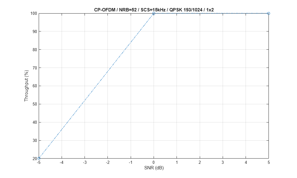
Display the measured throughput. This is calculated as the percentage of the maximum possible throughput of the link given the available resources for data transmission.
figure;
plot(simParameters.SNRIn,simThroughput*100./maxThroughput,'o-.')
xlabel('SNR (dB)'); ylabel('Throughput (%)'); grid on;
if (simParameters.PUSCH.TransformPrecoding)
    ofdmType = 'DFT-s-OFDM';
else
    ofdmType = 'CP-OFDM';
end
title(sprintf('%s / NRB=%d / SCS=%dkHz / %s %d/1024 / %dx%d', ...
    ofdmType,simParameters.Carrier.NSizeGrid,simParameters.Carrier.SubcarrierSpacing, ...
    simParameters.PUSCH.Modulation, ...
    round(simParameters.PUSCHExtension.TargetCodeRate*1024),simParameters.NTxAnts,simParameters.NRxAnts));

% Bundle key parameters and results into a combined structure for recording
simResults.simParameters = simParameters;
simResults.simThroughput = simThroughput;
simResults.maxThroughput = maxThroughput;
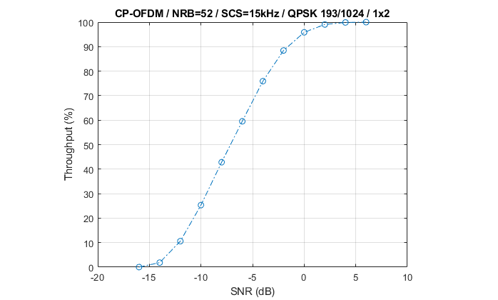
The figure below shows throughput results obtained simulating 10000 subframes (NFrames = 1000, SNRIn = -16:2:6).
References
[1] 3GPP TS 38.211. "NR; Physical channels and modulation." 3rd Generation Partnership Project; Technical Specification Group Radio Access Network.
[2] 3GPP TS 38.212. "NR; Multiplexing and channel coding." 3rd Generation Partnership Project; Technical Specification Group Radio Access Network.
[3] 3GPP TS 38.213. "NR; Physical layer procedures for control." 3rd Generation Partnership Project; Technical Specification Group Radio Access Network.
[4] 3GPP TS 38.214. "NR; Physical layer procedures for data." 3rd Generation Partnership Project; Technical Specification Group Radio Access Network.
[5] 3GPP TR 38.901. "Study on channel model for frequencies from 0.5 to 100 GHz." 3rd Generation Partnership Project; Technical Specification Group Radio Access Network.
Local Functions
function validateNumLayers(simParameters)
% Validate the number of layers, relative to the antenna geometry

    numlayers = simParameters.PUSCH.NumLayers;
    ntxants = simParameters.NTxAnts;
    nrxants = simParameters.NRxAnts;
    antennaDescription = sprintf('min(NTxAnts,NRxAnts) = min(%d,%d) = %d',ntxants,nrxants,min(ntxants,nrxants));
    if numlayers > min(ntxants,nrxants)
        error('The number of layers (%d) must satisfy NumLayers <= %s', ...
            numlayers,antennaDescription);
    end

    % Display a warning if the maximum possible rank of the channel equals
    % the number of layers
    if (numlayers > 2) && (numlayers == min(ntxants,nrxants))
        warning(['The maximum possible rank of the channel, given by %s, is equal to NumLayers (%d).' ...
            ' This may result in a decoding failure under some channel conditions.' ...
            ' Try decreasing the number of layers or increasing the channel rank' ...
            ' (use more transmit or receive antennas).'],antennaDescription,numlayers); %#ok<SPWRN>
    end

end

function plotLayerEVM(NSlots,nslot,pusch,siz,puschIndices,puschSymbols,puschEq)
% Plot EVM information

    persistent slotEVM;
    persistent rbEVM
    persistent evmPerSlot;

    if (nslot==0)
        slotEVM = comm.EVM;
        rbEVM = comm.EVM;
        evmPerSlot = NaN(NSlots,pusch.NumLayers);
        figure;
    end
    evmPerSlot(nslot+1,:) = slotEVM(puschSymbols,puschEq);
    subplot(2,1,1);
    plot(0:(NSlots-1),evmPerSlot,'o-');
    xlabel('Slot number');
    ylabel('EVM (%)');
    legend("layer " + (1:pusch.NumLayers),'Location','EastOutside');
    title('EVM per layer per slot');

    subplot(2,1,2);
    [k,~,p] = ind2sub(siz,puschIndices);
    rbsubs = floor((k-1) / 12);
    NRB = siz(1) / 12;
    evmPerRB = NaN(NRB,pusch.NumLayers);
    for nu = 1:pusch.NumLayers
        for rb = unique(rbsubs).'
            this = (rbsubs==rb & p==nu);
            evmPerRB(rb+1,nu) = rbEVM(puschSymbols(this),puschEq(this));
        end
    end
    plot(0:(NRB-1),evmPerRB,'x-');
    xlabel('Resource block');
    ylabel('EVM (%)');
    legend("layer " + (1:pusch.NumLayers),'Location','EastOutside');
    title(['EVM per layer per resource block, slot #' num2str(nslot)]);

    drawnow;

end

function [channel,simParameters] = createChannel(simParameters,waveformInfo)

    % Constructed the CDL or TDL channel model object
    if contains(simParameters.DelayProfile,'CDL','IgnoreCase',true)

        channel = nrCDLChannel; % CDL channel object

        % Swap transmit and receive sides as the default CDL channel is
        % configured for downlink transmissions.
        swapTransmitAndReceive(channel);

        % Turn the number of antennas into antenna panel array layouts. If
        % NRxAnts is not one of (1,2,4,8,16,32,64,128,256,512,1024), its value
        % is rounded up to the nearest value in the set. If NTxAnts is not 1 or
        % even, its value is rounded up to the nearest even number.
        channel = hArrayGeometry(channel,simParameters.NTxAnts,simParameters.NRxAnts,'uplink');
        simParameters.NTxAnts = prod(channel.TransmitAntennaArray.Size);
        simParameters.NRxAnts = prod(channel.ReceiveAntennaArray.Size);
    else
        channel = nrTDLChannel; % TDL channel object

        % Configure the channel to automatically select a sample rate for
        % generating channel coefficients
        channel.PathGainSampleRate = 'auto';

        % Swap transmit and receive sides as the default TDL channel is
        % configured for downlink transmissions
        swapTransmitAndReceive(channel);

        % Set the channel geometry
        channel.NumTransmitAntennas = simParameters.NTxAnts;
        channel.NumReceiveAntennas = simParameters.NRxAnts;
    end

    % Assign simulation channel parameters and waveform sample rate to the
    % object, and specify OFDM channel response as the channel response output
    % so that perfect channel estimate is calculated while filtering the signal
    channel.DelayProfile = simParameters.DelayProfile;
    if ~strcmp(channel.DelayProfile,"None")
        channel.DelaySpread = simParameters.DelaySpread;
        channel.MaximumDopplerShift = simParameters.MaximumDopplerShift;
        channel.SampleRate = waveformInfo.SampleRate;
    end
    channel.ChannelResponseOutput = 'ofdm-response';

end