NR SSB Beam Sweeping
This example shows how to employ beam sweeping at both the transmitter (gNB) and receiver (UE) ends of a 5G NR system. Using synchronization signal blocks (SSB), this example illustrates some of the beam management procedures used during initial access in an urban macrocell scenario, as defined in TR 38.901 and TR 38.843. To accomplish beam sweeping, the example uses Phased Array System Toolbox™ features.
Introduction
The support of millimeter wave (mmWave) frequencies requires directional links, which led to the specification of beam management procedures for initial access in NR. Beam management is a set of Layer 1 (physical) and Layer 2 (medium access control) procedures to acquire and maintain a set of beam pair links (a beam used at gNB paired with a beam used at UE). Beam management procedures are applied for both downlink and uplink transmission and reception. These procedures include:
Beam sweeping
Beam measurement
Beam determination
Beam reporting
Beam recovery
This example focuses on initial access procedures for idle users when a connection is established between UE and gNB. At the physical layer, using SSB transmitted as a burst in the downlink direction (gNB to UE), the example highlights both transmit/receive point (TRP) beam sweeping and UE beam sweeping to establish a beam pair link. Among the multiple beam management procedures, TR 38.802 defines this dual-end sweep as procedure P-1.
Once connected, the same beam pair link can be used for subsequent transmissions. If necessary, the beams are further refined using CSI-RS (for downlink) and SRS (for uplink). In case of beam failure, these pair links can be reestablished. For an example of beam pair refinement, see NR Downlink Transmit-End Beam Refinement Using CSI-RS.
This example generates an NR synchronization signal burst, beamforms each of the SSBs within the burst to sweep over the azimuth direction, transmits this beamformed signal over a MIMO fading channel, and processes this received signal over the multiple receive-end beams. The example measures the reference signal received power (RSRP) for each of the transmit-receive beam pairs (in a dual loop) and determines the beam pair link with the maximum RSRP. This beam pair link thus signifies the best beam-pair at transmit and receive ends for the simulated spatial scenario. This figure shows the main processing steps with the beam management ones highlighted in color.

The example uses the baseline system-level simulation assumptions for AI/ML from TR 38.843 Table 6.3.1-1. The main characteristics are:
1. Use TR 38.901 system-level channel model.
2. UEs are randomly distributed inside the first sector of a
three-sector cell.
3. The number of transmit and receive beams depends on the beamwidth.
While minimizing the number of beams, the example selects enough beams
to cover the full area. By default, the example considers ten transmit
beams and seven receive beams, according to the antenna specifications
defined in TR 38.843 Table 6.3.1-1.
Simulation Parameters
Define system parameters for the example. Modify these parameters to explore their impact on the system.
The example uses these parameters:
Cell ID for a single-cell scenario with a single BS and UE
Frequency range, as a string to designate FR1 or FR2 operation
Center frequency, in Hz, dependent on the frequency range
Synchronization signal block pattern as one of Case A/B/C for FR1 and Case D/E for FR2. This also selects the subcarrier spacing.
Transmit and receive antenna arrays, as phased.NRRectangularPanelArray objects
Transmit and receive azimuthal sweep limits in degrees to specify the starting and ending azimuth angles for the sweep
Transmit and receive elevation sweep limits in degrees to specify the starting and ending elevation angles for the sweep
Enable or disable elevation sweep for both transmit and receive ends.
Intersite distance, which defines the size of the cell
Transmit power and noise figure at the receive end
RSRP measurement mode for SSB
prm.NCellID = 1;                    % Cell ID
prm.FrequencyRange = 'FR2';         % Frequency range: 'FR1' or 'FR2'
prm.Scenario = 'UMa';               % Scenario: 'UMa', 'UMi', or 'RMa'
prm.CenterFrequency = 30e9;         % Hz
prm.SSBlockPattern = 'Case D';      % Case A/B/C/D/E

% Number of transmitted blocks. Set it to empty to let the example use
% the minimum number that ensures a full coverage of the 120-degree
% sector without overlapping of beams or gaps in the coverage
prm.NumSSBlocks = [];

prm.InterSiteDistance = 200;        % meters
prm.PowerBSs = 40;                  % dBm
prm.UENoiseFigure = 10;             % UE receiver noise figure in dB

% Enable or disable elevation sweep.
prm.ElevationSweep = false;

% RSRP measurement mode for SSB: 'SSSonly' uses SSS alone and 'SSSwDMRS'
% uses SSS and PBCH DM-RS.
prm.RSRPMode = 'SSSwDMRS';
The example uses a MIMO fading channel that has non line-of-sight (NLOS) components, which can make the visual inspection of the beams difficult. To see if the selected transmit and receive beams point at each other in the MIMO channel plot, force the channel to be a line-of-sight (LOS) channel.
setLOSPathOnly = false;
Antenna Array Configuration
Define the trasmit antenna array as a rectangular array with 4-by-8 cross-polarized elements, as defined in TR 38.843 Table 6.3.1-1. The example considers the base station covering the first of a three-sector cell, as defined in TR 38.901 Table 7.8-1, where the first sector is centered at 30 degrees. Set the antenna sweep limits in azimuth to cover the entire 120-degree sector, considering that the antenna array points towards the center of the sector.
c = physconst('LightSpeed');    % Propagation speed
lambda = c/prm.CenterFrequency; % Wavelength

% Transmit array
prm.TransmitAntennaArray = phased.NRRectangularPanelArray(...
    Size=[4,8,1,1],...
    Spacing=[0.5,0.5,1,1]*lambda);

% Transmit azimuthal and elevation sweep limits in degrees
prm.TxAZlim = [-60 60];
prm.TxELlim = [-90 0];

% Define the transmit antenna downtilt angle in degrees. The default is the
% value defined in TR 38.843 Table 6.3.1-2.
prm.TxDowntilt = 110;
Define the receive antenna array as a rectangular array with 1-by-4 omnidirectional cross-polarized elements, as defined in TR 38.843 Table 6.3.1-1. Set the antenna sweep limits in azimuth to cover the half of the entire 360-degree space, considering that the antenna elements are omnidirectional.
% Receive array
prm.ReceiveAntennaArray = phased.NRRectangularPanelArray(...
    Size=[1,4,1,1],...
    Spacing=[0.5,0.5,1,1]*lambda,...
    ElementSet={phased.ShortDipoleAntennaElement,phased.ShortDipoleAntennaElement});
% Ensure that the two elements are cross polarized
prm.ReceiveAntennaArray.ElementSet{1}.AxisDirection = "Custom";
prm.ReceiveAntennaArray.ElementSet{1}.CustomAxisDirection = [0;  1; 1];
prm.ReceiveAntennaArray.ElementSet{2}.AxisDirection = "Custom";
prm.ReceiveAntennaArray.ElementSet{2}.CustomAxisDirection = [0; -1; 1];

% Receive azimuthal and elevation sweep limits in degrees
prm.RxAZlim = [-90 90];
prm.RxELlim = [0 90];

prm = validateParams(prm);
Synchronization Signal Burst Configuration
Set up the synchronization signal burst parameters by using the specified system parameters. For initial access, set the SSB periodicity to 20 ms. The example assumes the SSB is always in the first half of the frame.
txBurst = nrWavegenSSBurstConfig;
txBurst.BlockPattern = prm.SSBlockPattern;
txBurst.TransmittedBlocks = prm.SSBTransmitted;
txBurst.Period = 20;
txBurst.SubcarrierSpacingCommon = prm.SubcarrierSpacingCommon;

% Configure an nrDLCarrierConfig object to use the synchronization signal
% burst parameters and to disable other channels. This object will be used
% by nrWaveformGenerator to generate the SS burst waveform.

cfgDL = configureWaveformGenerator(prm,txBurst);
Refer to the tutorial Synchronization Signal Blocks and Bursts for more details on synchronization signal blocks and bursts.
Burst Generation
Create the SS burst waveform by calling the nrWaveformGenerator function. The generated waveform is not yet beamformed.
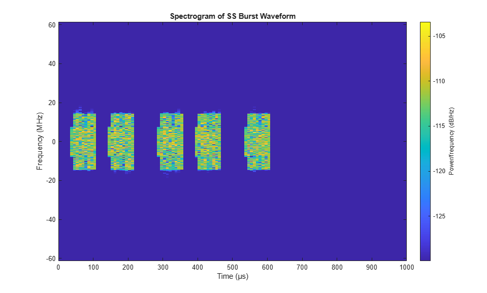
burstWaveform = nrWaveformGenerator(cfgDL);

% Get carrier object
ncellid = prm.NCellID;
carrier = nrCarrierConfig('NCellID',ncellid);
carrier.NSizeGrid = cfgDL.SCSCarriers{1}.NSizeGrid;
carrier.SubcarrierSpacing = cfgDL.SCSCarriers{1}.SubcarrierSpacing;

% Display spectrogram of SS burst waveform
figure;
ofdmInfo = nrOFDMInfo(carrier);
nfft = ofdmInfo.Nfft;
sampleRate = ofdmInfo.SampleRate;
spectrogram(burstWaveform,ones(nfft,1),0,nfft,'centered',sampleRate,'yaxis','MinThreshold',-130);
title('Spectrogram of SS Burst Waveform')
Channel Configuration
Configure a MIMO fading channel, channel, as defined in TR 38.901. Use the h38901Scenario and h38901Channel functions to create a channel between a base station and a UE randomly dropped in the first sector of a three-sector node.
% Specify the seed used to generate the channel and drop the UEs within the
% sector boundaries.
seed = 49;

% Use |h38901Scenario| to create an urban macrocell (UMa) scenario with a
% single cell and three sectors. The scenario considers spatial
% consistency, as defined in TR 38.901 Section 7.6.3-1.
s38901 = h38901Scenario(Scenario=prm.Scenario,...
    CarrierFrequency=prm.CenterFrequency,...
    InterSiteDistance=prm.InterSiteDistance,...
    NumCellSites=1,...
    NumSectors=3,...
    NumUEs=1,...
    ChosenUEs=true,...
    SpatialConsistency=true,...
    Wrapping=false,...
    Seed=seed);

% Create the channels for each sector, specifying the transmit and receive
% antenna arrays.
[channelsAll,chinfoAll] = createChannelLinks(s38901,...
    SampleRate=sampleRate,...
    DropMode="PathLoss",...
    TransmitAntennaArray=prm.TransmitAntennaArray,...
    ReceiveAntennaArray=prm.ReceiveAntennaArray,...
    FastFading=true);

% Get the channel and the channel information structure for the first
% sector.
channel = channelsAll(1,1,1);
chInfo = chinfoAll.AttachedUEInfo(1,1,1);

% Ensure that channel filtering is on to be able to pass the waveform
% through the channel
channel.SmallScale.ChannelFiltering = true;

if setLOSPathOnly
    channel = forceLOSChannel(prm,channel);
end

% Extract the position of the base station and the UE, together with the
% information on whether the UE is in line of sight (LOS) or not.
prm.posTx = chInfo.Config.BSPosition; % Transmit array position, [x,y,z], meters
prm.posRx = chInfo.Position;          % Receive array position, [x,y,z], meters
prm.LOS = channel.SmallScale.HasLOSCluster;

% Add transmit and receive array orientation info to the parameter structure
prm.TransmitArrayOrientation = channel.SmallScale.TransmitArrayOrientation';
prm.ReceiveArrayOrientation = channel.SmallScale.ReceiveArrayOrientation';

% Get the maximum channel delay
chInfo = info(channel.SmallScale);
maxChDelay = chInfo.MaximumChannelDelay;
Transmit-End Beam Sweeping
To achieve TRP beam sweeping, beamform each of the SS blocks in the generated burst using analog beamforming. Based on the number of SS blocks in the burst and the sweep ranges specified, determine both the azimuth and elevation directions for the different beams. Then beamform the individual blocks within the burst to each of these directions.
% Transmit beam angles in azimuth and elevation, equi-spaced
numTxBeams = prm.NumTxBeams;
arrayTx = prm.TransmitAntennaArray;
azBW = beamwidth(arrayTx,prm.CenterFrequency,'Cut','Azimuth');
elBW = beamwidth(arrayTx,prm.CenterFrequency,'Cut','Elevation');
txBeamAng = hGetBeamSweepAngles(numTxBeams,prm.TxAZlim,prm.TxELlim, ...
    azBW,elBW,prm.ElevationSweep);
% Account for the antenna downtilt
elOffset = 90 - prm.TxDowntilt;
txBeamAng(2,:) = txBeamAng(2,:) + elOffset;

% For evaluating transmit-side steering weights
SteerVecTx = phased.SteeringVector('SensorArray',arrayTx, ...
    'PropagationSpeed',c);

% Get the set of OFDM symbols and subcarriers occupied by each SSB
numBlocks = length(txBurst.TransmittedBlocks);
burstStartSymbols = hSSBurstStartSymbols(txBurst.BlockPattern,numBlocks);
burstStartSymbols = burstStartSymbols(txBurst.TransmittedBlocks==1);
burstOccupiedSymbols = burstStartSymbols.' + (1:4);
burstOccupiedSubcarriers = carrier.NSizeGrid*6 + (-119:120).';

% Apply steering per OFDM symbol for each SSB
gridSymLengths = repmat(ofdmInfo.SymbolLengths,1,cfgDL.NumSubframes);
%   repeat burst over numTx to prepare for steering
strTxWaveform = repmat(burstWaveform,1,prm.NumTx)./sqrt(prm.NumTx);
for txBeamIdx = 1:numTxBeams

    % Extract SSB waveform from burst
    blockSymbols = burstOccupiedSymbols(txBeamIdx,:);
    startSSBInd = sum(gridSymLengths(1:blockSymbols(1)-1))+1;
    endSSBInd = sum(gridSymLengths(1:blockSymbols(4)));
    ssbWaveform = strTxWaveform(startSSBInd:endSSBInd,1);

    % Generate weights for steered direction
    wT = SteerVecTx(prm.CenterFrequency,txBeamAng(:,txBeamIdx));

    % Beamforming: Apply weights per transmit element to SSB
    strTxWaveform(startSSBInd:endSSBInd,:) = ssbWaveform*(wT');

end

% Adjust the beamformed waveform according to the base station power
pref = sum(rms(strTxWaveform).^2);
txWaveform = strTxWaveform*1/sqrt(pref)*sqrt(10^((prm.PowerBSs-30)/10));
The beamformed burst waveform is then transmitted over the channel.
% Pad the waveform to ensure the channel filter is fully flushed
nT = size(txWaveform,2);
dlWaveform = [txWaveform; zeros(maxChDelay,nT)];

% Pass the waveform through the channel
rxWaveform = channel.SmallScale(dlWaveform);
rxWaveform = rxWaveform*db2mag(channel.LargeScale); % Account for the path loss

% Apply AWGN
rng(seed); % Set RNG state for repeatability
rxWaveform = hAWGN(rxWaveform,prm.UENoiseFigure,sampleRate);
Receive-End Beam Sweeping and Measurement
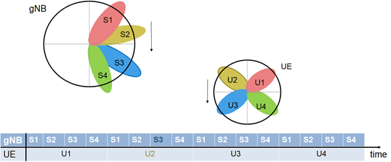
For receive-end beam sweeping, the transmitted beamformed burst waveform is received successively over each receive beam. For N transmit beams and M receive beams in procedure P-1, each of the N beams is transmitted M times from gNB so that each transmit beam is received over the M receive beams. For simplicity, the example generates one burst only, but to mimic the burst reception over the air M times, the receiver processes this single burst M times.
This figure shows a beam-based diagram for the sweeps at both gNB and UE for N = M = 4, in the azimuthal plane. The diagram shows the time taken for the dual sweep, where each interval at gNB corresponds to an SSB and each interval at the UE corresponds to the SS burst. For the depicted scenario, beams S3 and U2 are highlighted as the selected beam-pair link notionally. The example implements the dual-sweep over a time duration of N*M time instants.
The receive processing of the transmitted burst includes:
Receive-end beam-combining
Timing correction
OFDM demodulation
Extracting the known SSB grid
Measuring the RSRP based on the specified measurement mode
The processing repeats these steps for each of the receive beams, then selects the best beam-pair based on the complete set of measurements made.
To highlight beam sweeping, the example assumes known SSB information at the receiver. For more details on recovery processing see NR Cell Search and MIB and SIB1 Recovery.
For the idle mode SS-RSRP measurement, use either only the secondary synchronization signals (SSS) or the physical broadcast channel (PBCH) demodulation reference signals (DM-RS) in addition to the SSS, as described in TS 38.215 Section 5.1.1. Specify this by the RSRPMode parameter of the example.
% Receive beam angles in azimuth and elevation, equi-spaced
numRxBeams = prm.NumRxBeams;
arrayRx = prm.ReceiveAntennaArray;
azBW = beamwidth(arrayRx,prm.CenterFrequency,'Cut','Azimuth');
elBW = beamwidth(arrayRx,prm.CenterFrequency,'Cut','Elevation');
rxBeamAng = hGetBeamSweepAngles(numRxBeams,prm.RxAZlim,prm.RxELlim, ...
    azBW,elBW,prm.ElevationSweep);

% For evaluating receive-side steering weights
SteerVecRx = phased.SteeringVector('SensorArray',arrayRx, ...
    'PropagationSpeed',c);

% Loop over all receive beams
rsrp = -inf(numRxBeams,numTxBeams);
for rIdx = 1:numRxBeams

    % Generate weights for steered direction
    wR = SteerVecRx(prm.CenterFrequency,rxBeamAng(:,rIdx));

    % Beam combining: Apply weights per receive element
    strRxWaveform = rxWaveform*conj(wR);

    % Correct timing
    offset = hSSBurstTimingOffset(strRxWaveform,carrier,ofdmInfo,burstOccupiedSymbols);
    if offset > maxChDelay
        % If the receiver cannot compute a valid timing offset, the receive
        % power of the waveform is too low. Continue to the next receive
        % beam.
        continue
    end
    strRxWaveformS = strRxWaveform(1+offset:end,:);

    % OFDM Demodulate
    rxGrid = nrOFDMDemodulate(carrier,strRxWaveformS);

    % Loop over all SSBs in rxGrid (transmit end)
    for tIdx = 1:numTxBeams
        % Get each SSB grid
        rxSSBGrid = rxGrid(burstOccupiedSubcarriers, ...
            burstOccupiedSymbols(tIdx,:),:);

        % Compute the synchronization signal RSRP
        rsrp(rIdx,tIdx) = hSSBurstRSRP(rxSSBGrid,ncellid,txBurst.TransmittedBlocks,tIdx,prm.RSRPMode);
    end
end
Beam Determination
After the dual-end sweep and measurements are complete, determine the best beam-pair link based on the RSRP measurement.
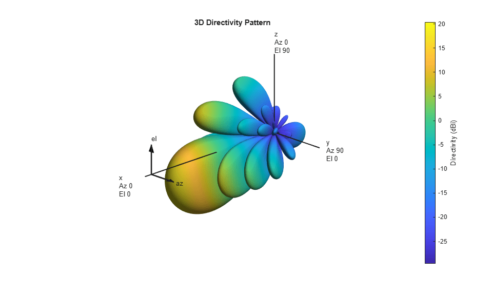
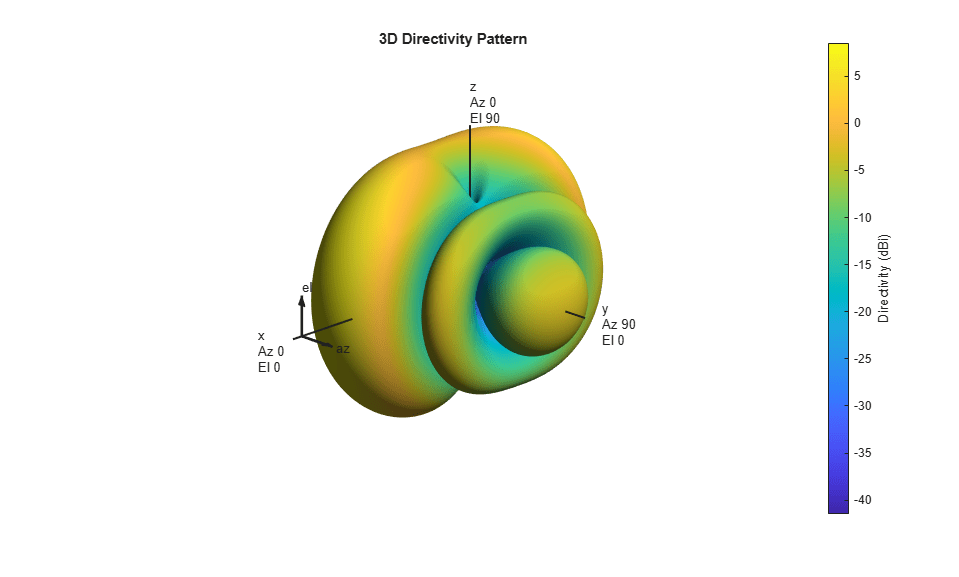
[~,optBeamPairIdx] = max(rsrp,[],'all','linear'); % First occurrence is output
% optBeamPairIdx is column-down first (for receive), then across columns (for transmit)
[rxBeamID,txBeamID] = ind2sub([numRxBeams numTxBeams],optBeamPairIdx);

% Display the selected beam pair
disp("Selected beam pair with RSRP: " + rsrp(optBeamPairIdx) + " dBm");
disp("  Transmit #"  + compose('%-3d',txBeamID) + ...
     " (Azimuth: "   + compose('%7.2f',txBeamAng(1,txBeamID)) + ...
     ", Elevation: " + compose('%7.2f',txBeamAng(2,txBeamID)) + ")");
disp("  Receive  #"  + compose('%-3d',rxBeamID) + ...
     " (Azimuth: "   + compose('%7.2f',rxBeamAng(1,rxBeamID)) + ...
     ", Elevation: " + compose('%7.2f',rxBeamAng(2,rxBeamID)) + ")");

% Display final beam pair patterns
figure(Name="Selected Transmit Array Response Pattern");
wT = SteerVecTx(prm.CenterFrequency,txBeamAng(:,txBeamID));
pattern(arrayTx,prm.CenterFrequency,PropagationSpeed=c,Weights=wT);

figure(Name="Selected Receive Array Response Pattern");
wR = SteerVecRx(prm.CenterFrequency,rxBeamAng(:,rxBeamID));
pattern(arrayRx,prm.CenterFrequency,PropagationSpeed=c,Weights=wR);
Selected beam pair with RSRP: 22.3728 dBm
  Transmit #4   (Azimuth:  -12.00, Elevation:  -20.00)
  Receive  #3   (Azimuth:  -12.86, Elevation:    0.00)
Plot TR 38.901 scenario with tx, rx, and determined beams. In case of strong NLOS clusters in the channel, the beam pair that maximizes the RSRP value can point slightly off from each other. Different heights between the base station and the UE can also affect the visualization. By default, the example only shows the optimal beams. To see all beams in the plot, set plotAllBeams to true.
dataInfo = struct();
dataInfo.PosBS = prm.posTx;
dataInfo.PosUE = prm.posRx;
dataInfo.TransmitArrayOrientation = channel.SmallScale.TransmitArrayOrientation';
dataInfo.ReceiveArrayOrientation = channel.SmallScale.ReceiveArrayOrientation';
plotAllBeams = false;
hPlotSpatial38901Scene(prm,dataInfo,optBeamPairIdx,plotAllBeams);
if ~prm.ElevationSweep
    view(2);
end
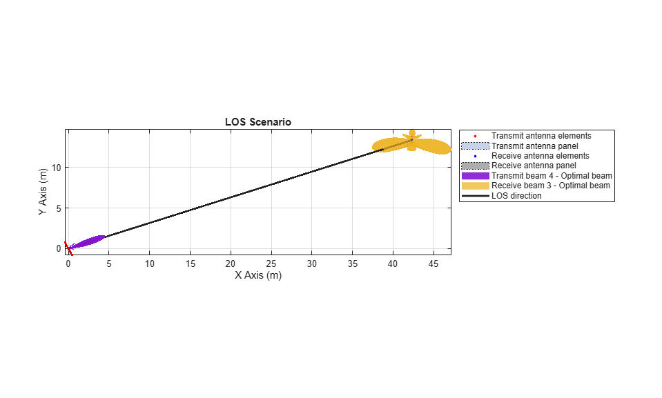
These plots highlight the transmit directivity pattern, receive directivity pattern, and the spatial scene, respectively. The results are dependent on the individual beam directions used for the sweeps. The spatial scene offers a combined view of the transmit and receive arrays and the respective determined beams.
Summary and Further Exploration
This example highlights the P-1 beam management procedure by using synchronization signal blocks for transmit-end and receive-end beam sweeping. By measuring the reference signal received power for SSBs, you can identify the best beam pair link for a selected spatial environment.
The example allows variation on frequency range, scenario, SSB block pattern, number of SSBs, transmit and receive antenna arrays, transmit and receive sweep ranges, and the measuring mode. To see the impact of parameters on the beam selection, experiment with different values. The example shows a simplified receive processing to highlight the beamforming aspects.
For an example of the P-2 procedures of transmit-end beam sweeping using CSI-RS signals for the downlink, see NR Downlink Transmit-End Beam Refinement Using CSI-RS. You can use these procedures for beam refinement and adjustment in the connected mode, once the initial beam pair links are established.
References
3GPP TR 38.802. "Study on New Radio access technology physical layer aspects." 3rd Generation Partnership Project; Technical Specification Group Radio Access Network.
3GPP TR 38.843, "Study on Artificial Intelligence (AI)/Machine Learning (ML) for NR air interface." 3rd Generation Partnership Project; Technical Specification Group Radio Access Network.
3GPP TR 38.901, "Study on channel model for frequencies from 0.5 to 100 GHz." 3rd Generation Partnership Project; Technical Specification Group Radio Access Network.
Giordani, M., M. Polese, A. Roy, D. Castor, and M. Zorzi. "A tutorial on beam management for 3GPP NR at mmWave frequencies." IEEE Comm. Surveys & Tutorials, vol. 21, No. 1, Q1 2019.
3GPP TS 38.211. "NR; Physical channels and modulation." 3rd Generation Partnership Project; Technical Specification Group Radio Access Network.
3GPP TS 38.215. "NR; Physical layer measurements." 3rd Generation Partnership Project; Technical Specification Group Radio Access Network.
Giordani, M., M. Polese, A. Roy, D. Castor, and M. Zorzi. "Standalone and non-standalone beam management for 3GPP NR at mmWaves." IEEE Comm. Mag., April 2019, pp. 123-129.
Onggosanusi, E., S. Md. Rahman, et al. "Modular and high-resolution channel state information and beam management for 5G NR." IEEE Comm. Mag., March 2018, pp. 48-55.
Local Functions
function prm = validateParams(prm)
    % Validate user specified parameters and return updated parameters
    %
    % Only cross-dependent checks are made for parameter consistency.

    if strcmpi(prm.FrequencyRange,'FR1')
        if prm.CenterFrequency > 7.125e9 || prm.CenterFrequency < 410e6
            error(['Specified center frequency is outside the FR1 ' ...
                'frequency range (410 MHz - 7.125 GHz).']);
        end
        if strcmpi(prm.SSBlockPattern,'Case D') ||  ...
           strcmpi(prm.SSBlockPattern,'Case E')
            error(['Invalid SSBlockPattern for selected FR1 frequency ' ...
                'range. SSBlockPattern must be one of ''Case A'' or ' ...
                '''Case B'' or ''Case C'' for FR1.']);
        end
    else % 'FR2'
        if prm.CenterFrequency > 52.6e9 || prm.CenterFrequency < 24.25e9
            error(['Specified center frequency is outside the FR2 ', ...
                   'frequency range (24.25 GHz - 52.6 GHz).']);
        end
        if ~(strcmpi(prm.SSBlockPattern,'Case D') || ...
                strcmpi(prm.SSBlockPattern,'Case E'))
            error(['Invalid SSBlockPattern for selected FR2 frequency ' ...
                'range. SSBlockPattern must be either ''Case D'' or ' ...
                '''Case E'' for FR2.']);
        end
    end

    % Verify that there are multiple TX and Rx antennas
    prm.NumTx = getNumElements(prm.TransmitAntennaArray);
    prm.NumRx = getNumElements(prm.ReceiveAntennaArray);
    if prm.NumTx==1 || prm.NumRx==1
        error(['Number of transmit or receive antenna elements must be', ...
               ' greater than 1.']);
    end

    if ~( strcmpi(prm.RSRPMode,'SSSonly') || ...
          strcmpi(prm.RSRPMode,'SSSwDMRS') )
        error(['Invalid RSRP measuring mode. Specify either ', ...
               '''SSSonly'' or ''SSSwDMRS'' as the mode.']);
    end

    % Number of beams at transmit end
    % Assume a number of beams so that the beams span the entire 120-degree
    % sector, with a maximum of 64 beams, as mentioned in TR 38.843 Table
    % 6.3.1-1
    % Assume the number of transmitted blocks is the same as the number of
    % beams at transmit end
    if prm.FrequencyRange=="FR1"
        maxNumSSBBlocks = 8;
    else % FR2
        maxNumSSBBlocks = 64;
    end
    if isempty(prm.NumSSBlocks)
        % The number of blocks/beams is automatically generated as the
        % minimum needed to cover the full azimuth sweep
        azTxBW = beamwidth(prm.TransmitAntennaArray,prm.CenterFrequency,'Cut','Azimuth');
        numAZTxBeams = round(diff(prm.TxAZlim)/azTxBW);

        if prm.ElevationSweep
            % If elevation sweep is enabled, consider elevation as well in
            % the computation of the number of blocks/beams needed.
            elTxBW = beamwidth(prm.TransmitAntennaArray,prm.CenterFrequency,'Cut','Elevation');
            numELTxBeams = round(diff(prm.TxELlim)/elTxBW);
        else
            numELTxBeams = 1;
        end

        prm.NumTxBeams = min(numAZTxBeams*numELTxBeams, maxNumSSBBlocks);
        prm.NumSSBlocks = prm.NumTxBeams;
    else
        % The number of blocks/beams is defined by the user
        if prm.NumSSBlocks>maxNumSSBBlocks
            error("Invalid number of SSB blocks. For " + prm.FrequencyRange + ...
                ", there can be only up to " + maxNumSSBBlocks + " blocks.");
        end
        prm.NumTxBeams = prm.NumSSBlocks;
    end
    prm.SSBTransmitted = [ones(1,prm.NumTxBeams) zeros(1,maxNumSSBBlocks-prm.NumTxBeams)];

    % Number of beams at receive end
    % Assume a number of beams so that the beams cover the full azimuth
    % sweep, with a maximum of 8 beams, as mentioned in TR 38.843 Table
    % 6.3.1-1.
    azRxBW = beamwidth(prm.ReceiveAntennaArray,prm.CenterFrequency,'Cut','Azimuth');
    numAZRxBeams = round(diff(prm.RxAZlim)/azRxBW);
    if prm.ElevationSweep
        % If elevation sweep is enabled, consider elevation as well in
        % the computation of the number of blocks/beams needed.
        elRxBW = beamwidth(prm.ReceiveAntennaArray,prm.CenterFrequency,'Cut','Elevation');
        numELRxBeams = round(diff(prm.RxELlim)/elRxBW);
    else
        numELRxBeams = 1;
    end
    prm.NumRxBeams = min(numAZRxBeams*numELRxBeams, 8);

    % Select SCS based on SSBlockPattern
    switch lower(prm.SSBlockPattern)
        case 'case a'
            scs = 15;
            cbw = 10;
            scsCommon = 15;
        case {'case b', 'case c'}
            scs = 30;
            cbw = 25;
            scsCommon = 30;
        case 'case d'
            scs = 120;
            cbw = 100;
            scsCommon = 120;
        case 'case e'
            scs = 240;
            cbw = 200;
            scsCommon = 120;
    end
    prm.SCS = scs;
    prm.ChannelBandwidth = cbw;
    prm.SubcarrierSpacingCommon = scsCommon;
end

function cfgDL = configureWaveformGenerator(prm,txBurst)
    % Configure an nrDLCarrierConfig object to be used by nrWaveformGenerator
    % to generate the SS burst waveform.

    % Calculate the minimum number of subframes for the given number of
    % transmitted blocks to avoid generating a waveform that is longer than
    % needed
    carrier = nrCarrierConfig(SubcarrierSpacing=prm.SCS);
    symbolsPerSubframe = carrier.SymbolsPerSlot*carrier.SlotsPerSubframe;
    numBlocks = length(txBurst.TransmittedBlocks);
    burstStartSymbols = hSSBurstStartSymbols(txBurst.BlockPattern,numBlocks);
    burstStartSymbols = burstStartSymbols(txBurst.TransmittedBlocks==1);
    burstOccupiedSymbols = burstStartSymbols.' + (1:4);
    numSubframes = ceil(burstOccupiedSymbols(prm.NumSSBlocks,end)/symbolsPerSubframe);

    cfgDL = nrDLCarrierConfig;
    cfgDL.SCSCarriers{1}.SubcarrierSpacing = prm.SCS;
    if (prm.SCS==240)
        cfgDL.SCSCarriers = [cfgDL.SCSCarriers cfgDL.SCSCarriers];
        cfgDL.SCSCarriers{2}.SubcarrierSpacing = prm.SubcarrierSpacingCommon;
        cfgDL.BandwidthParts{1}.SubcarrierSpacing = prm.SubcarrierSpacingCommon;
    else
        cfgDL.BandwidthParts{1}.SubcarrierSpacing = prm.SCS;
    end
    cfgDL.PDSCH{1}.Enable = false;
    cfgDL.PDCCH{1}.Enable = false;
    cfgDL.ChannelBandwidth = prm.ChannelBandwidth;
    cfgDL.FrequencyRange = prm.FrequencyRange;
    cfgDL.NCellID = prm.NCellID;
    cfgDL.NumSubframes = numSubframes;
    cfgDL.WindowingPercent = 0;
    cfgDL.SSBurst = txBurst;

end

function rxWaveform = hAWGN(rxWaveform,noiseFigure,sampleRate)
    % Add noise to the received waveform

    persistent kBoltz;
    if isempty(kBoltz)
        kBoltz = physconst('Boltzmann');
    end

    % Calculate the required noise power spectral density
    NF = 10^(noiseFigure/10);
    N0 = sqrt(kBoltz*sampleRate*290*NF);

    % Establish dimensionality based on the received waveform
    [T,Nr] = size(rxWaveform);

    % Create noise
    noise = N0*randn([T Nr],'like',1i);

    % Add noise to the received waveform
    rxWaveform = rxWaveform + noise;
end

function channel = forceLOSChannel(prm,channel)
    % Force the channel to be LOS
    if channel.SmallScale.HasLOSCluster
        % The channel is already LOS
        return;
    end

    % Turn on the HasLOSCluster flag
    channel.SmallScale.HasLOSCluster = true;

    % Ensure the array paths are pointing in the right direction and remove
    % all NLOS clusters
    d = prm.posRx-prm.posTx;
    [az,el,~] = cart2sph(d(1),d(2),d(3));
    channel.SmallScale.AnglesAoD = rad2deg(az);
    channel.SmallScale.AnglesZoD = 90-rad2deg(el);
    channel.SmallScale.AnglesAoA = channel.SmallScale.AnglesAoD(1) + 180;
    channel.SmallScale.AnglesZoA = 180-channel.SmallScale.AnglesZoD(1);
    channel.SmallScale.PathDelays = channel.SmallScale.PathDelays(1);
    channel.SmallScale.AveragePathGains = channel.SmallScale.AveragePathGains(1);

    channel.SmallScale.NumStrongestClusters = 0;
    channel.SmallScale.XPR = channel.SmallScale.XPR(1,:);
    channel.SmallScale.RayCoupling = channel.SmallScale.RayCoupling(1,:,:);
    channel.SmallScale.InitialPhases = channel.SmallScale.InitialPhases(1,:,:);

end
See Also
Objects
phased.SteeringVector(Phased Array System Toolbox)