NR Downlink Transmit-End Beam Refinement Using CSI-RS
This example demonstrates the downlink transmit-end beam refinement procedure using the channel state information reference signal (CSI-RS) from 5G Toolbox™. The example shows how to transmit multiple CSI-RS resources in different directions in a scattering environment and how to select the optimal transmit beam based on reference signal received power (RSRP) measurements.
Introduction
In NR 5G, frequency range 2 (FR2) operates at millimeter wave (mmWave) frequencies (24.25 GHz to 52.6 GHz). As the frequency increases, the transmitted signal is prone to high path loss and penetration loss, which affects the link budget. To improve the gain and directionality of the transmission and reception of the signals at higher frequencies, beamforming is essential. Beam management is a set of Layer 1 (physical layer) and Layer 2 (medium access control) procedures to establish and retain an optimal beam pair (transmit beam and a corresponding receive beam) for good connectivity. TR 38.802 Section 6.1.6.1 [1] defines beam management as three procedures:
Procedure 1 (P-1): This procedure focuses on the initial acquisition based on synchronization signal blocks (SSB). During the initial acquisition, beam sweeping takes place at both transmit and receive ends to select the best beam pair based on the RSRP measurements. In general, the selected beams are wide and may not be an optimal beam pair for the data transmission and reception. For more details on this procedure, see NR SSB Beam Sweeping.
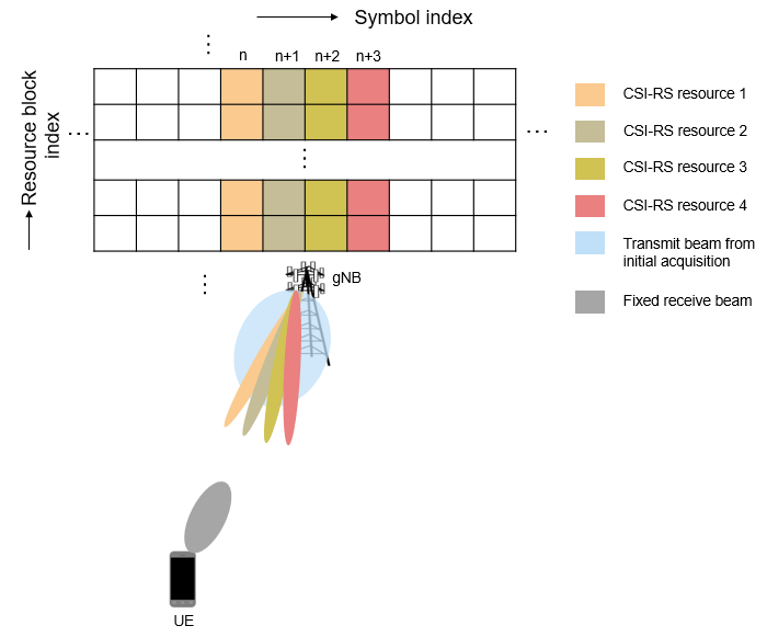
Procedure 2 (P-2): This procedure focuses on transmit-end beam refinement, where the beam sweeping happens at the transmit end by keeping the receive beam fixed. The procedure is based on non-zero-power CSI-RS (NZP-CSI-RS) for downlink transmit-end beam refinement and sounding reference signal (SRS) for uplink transmit-end beam refinement.
After the initial beam establishment, obtaining a unicast data transmission with high directivity and high gain requires a beam much finer than the SSB beam. Therefore, a set of reference signal resources are configured and transmitted in different directions by using finer beams within the angular range of the beam from the initial acquisition process. Then the user equipment (UE) or the access network node (gNB) measures all these beams by capturing the signals with a fixed receive beam. Finally, the best transmit beam is selected based on the RSRP measurements on all transmit beams.
Procedure 3 (P-3): This procedure focuses on receive-end beam adjustment, where the beam sweeping happens at the receive end given the current transmit beam. This process aims to find the best receive beam, which can be a neighbor beam or a refined beam. For this procedure, a set of reference signal resources (NZP-CSI-RS for downlink and SRS for uplink) are transmitted with the same transmit beam and the UE or gNB receives the signal using different beams from different directions covering an angular range. Finally, the best receive beam is selected based on the RSRP measurements on all receive beams.
This example focuses on downlink beam refinement at the transmitter. The example works for both frequency range 1 (FR1) and frequency range 2 (FR2) of NR 5G. This figure depicts the transmit-end beam refinement procedure, considering four NZP-CSI-RS resources transmitted in four different directions.
This figure shows the main processing steps of this example with the transmit-end beam refinement process-related steps in color.

Generate CSI-RS Resources
Configure Carrier
Create a carrier configuration object representing a 50 MHz carrier with subcarrier spacing of 30 kHz.
carrier = nrCarrierConfig;
% Maximum transmission bandwidth configuration for 50 MHz carrier with 30 kHz subcarrier spacing
carrier.NSizeGrid = 133;
carrier.SubcarrierSpacing = 30;
carrier.NSlot = 0;
carrier.NFrame = 0
carrier =
nrCarrierConfig with properties:
NCellID: 1
SubcarrierSpacing: 30
CyclicPrefix: 'normal'
NSizeGrid: 133
NStartGrid: 0
NSlot: 0
NFrame: 0
IntraCellGuardBands: [0×2 double]
Read-only properties:
SymbolsPerSlot: 14
SlotsPerSubframe: 2
SlotsPerFrame: 20
Configure CSI-RS
Create a CSI-RS configuration object representing an NZP-CSI-RS resource set with numNZPRes number of NZP-CSI-RS resources. For Layer 1 RSRP measurements, configure all the CSI-RS resources in a resource set with the same number of antenna ports (either single-port or dual-port), as specified in TS 38.215 Section 5.1.2 [2] or TS 38.214 Section 5.1.6.1.2 [3]. This example works for single-port CSI-RS.
numNZPRes = 12;
csirs = nrCSIRSConfig;
csirs.CSIRSType = repmat({'nzp'},1,numNZPRes);
csirs.CSIRSPeriod = 'on';
csirs.Density = repmat({'one'},1,numNZPRes);
csirs.RowNumber = repmat(2,1,numNZPRes);
csirs.SymbolLocations = {0,1,2,3,4,5,6,7,8,9,10,11};
csirs.SubcarrierLocations = repmat({0},1,numNZPRes);
csirs.NumRB = 25
csirs =
nrCSIRSConfig with properties:
CSIRSType: {'nzp' 'nzp' 'nzp' 'nzp' 'nzp' 'nzp' 'nzp' 'nzp' 'nzp' 'nzp' 'nzp' 'nzp'}
CSIRSPeriod: 'on'
RowNumber: [2 2 2 2 2 2 2 2 2 2 2 2]
Density: {'one' 'one' 'one' 'one' 'one' 'one' 'one' 'one' 'one' 'one' 'one' 'one'}
SymbolLocations: {[0] [1] [2] [3] [4] [5] [6] [7] [8] [9] [10] [11]}
SubcarrierLocations: {[0] [0] [0] [0] [0] [0] [0] [0] [0] [0] [0] [0]}
NumRB: 25
RBOffset: 0
NID: 0
Read-only properties:
NumCSIRSPorts: [1 1 1 1 1 1 1 1 1 1 1 1]
CDMType: {'noCDM' 'noCDM' 'noCDM' 'noCDM' 'noCDM' 'noCDM' 'noCDM' 'noCDM' 'noCDM' 'noCDM' 'noCDM' 'noCDM'}
% Validate CSI-RS antenna ports
validateCSIRSPorts(csirs);

% Get the binary vector to represent the presence of each CSI-RS resource
% in a specified slot
csirsTransmitted = getActiveCSIRSRes(carrier,csirs);
Configure the power scaling of all NZP-CSI-RS resources in decibels (dB).
powerCSIRS = 0;
Generate CSI-RS Symbols and Indices
Generate CSI-RS symbols and indices by using the carrier and csirs configuration objects. To distinguish each CSI-RS resource output separately, specify the OutputResourceFormat,'cell' name-value pair.
csirsSym = nrCSIRS(carrier,csirs,'OutputResourceFormat','cell')
csirsSym=1×12 cell array
    {25×1 double}    {25×1 double}    {25×1 double}    {25×1 double}    {25×1 double}    {25×1 double}    {25×1 double}    {25×1 double}    {25×1 double}    {25×1 double}    {25×1 double}    {25×1 double}
csirsInd = nrCSIRSIndices(carrier,csirs,'OutputResourceFormat','cell')
csirsInd=1×12 cell array
    {25×1 uint32}    {25×1 uint32}    {25×1 uint32}    {25×1 uint32}    {25×1 uint32}    {25×1 uint32}    {25×1 uint32}    {25×1 uint32}    {25×1 uint32}    {25×1 uint32}    {25×1 uint32}    {25×1 uint32}
Configure Antenna Arrays and Scatterers
Configure Transmit and Receive Antenna Arrays
Configure the carrier frequency and the signal propagation speed.
% Set the carrier frequency
fc = 3.5e9;
freqRange = validateFc(fc);

% Set the propagation speed
c = physconst('LightSpeed');
% Calculate wavelength
lambda = c/fc;
Configure the size of transmit and receive antenna arrays as a two-element vector, where the first element represents the number of rows and the second element represents the number of columns in the antenna array.
txArySize = [8 8];
rxArySize = [2 2];
Calculate the total number of transmit and receive antenna elements.
nTx = prod(txArySize);
nRx = prod(rxArySize);
Configure the positions of transmit and receive antenna arrays. Then calculate the free space path loss based on the spatial separation between transmit and receive antenna array positions.
% Configure antenna array positions
txArrayPos = [0;0;0];
rxArrayPos = [100;50;0];

% Calculate the free space path loss
toRxRange = rangeangle(txArrayPos,rxArrayPos);
spLoss = fspl(toRxRange,lambda);
Configure the uniform linear array (ULA) or uniform rectangular array (URA) based on the sizes of antennas arrays.
% Initialize the flags to choose between URA and ULA
isTxRectArray = false;
isRxRectArray = false;

% Enable isTxRectArray if both the number of rows and columns of transmit
% antenna array are greater than one
if ~any(txArySize == 1)
    isTxRectArray = true;
end
% Enable isRxRectArray if both the number of rows and columns of receive
% antenna array are greater than one
if ~any(rxArySize == 1)
    isRxRectArray = true;
end

% Configure the transmit and receive antenna elements
txAntenna = phased.IsotropicAntennaElement('BackBaffled',true);  % To avoid transmission beyond +/- 90
                                                                 % degrees from the broadside, baffle
                                                                 % the back of the transmit antenna
                                                                 % element by setting the BackBaffled
                                                                 % property to true
rxAntenna = phased.IsotropicAntennaElement('BackBaffled',false); % To receive the signal from 360 degrees,
                                                                 % set the BackBaffled property to false

% Configure transmit antenna array
if isTxRectArray
    % Create a URA System object for signal transmission
    txArray = phased.URA('Element',txAntenna,'Size',txArySize,'ElementSpacing',lambda/2);
else
    % Create a ULA System object for signal transmission
    txArray = phased.ULA('Element',txAntenna,'NumElements',nTx,'ElementSpacing',lambda/2);
end

% Configure receive antenna array
if isRxRectArray
    % Create a URA System object for signal reception
    rxArray = phased.URA('Element',rxAntenna,'Size',rxArySize,'ElementSpacing',lambda/2);
else
    % Create a ULA System object for signal reception
    rxArray = phased.ULA('Element',rxAntenna,'NumElements',nRx,'ElementSpacing',lambda/2);
end
Configure Scatterers
fixedScatMode = true;
rng(42);
if fixedScatMode
    % Fixed single scatterer location
    numScat = 1;
    scatPos = [60;10;15];
else
    % Generate scatterers at random positions
    numScat = 10; %#ok<UNRCH>
    azRange = -180:180;
    randAzOrder = randperm(length(azRange));
    elRange = -90:90;
    randElOrder = randperm(length(elRange));
    azAngInSph = deg2rad(azRange(randAzOrder(1:numScat)));
    elAngInSph = deg2rad(elRange(randElOrder(1:numScat)));
    r = 20;

    % Transform spherical coordinates to Cartesian coordinates
    [x,y,z] = sph2cart(azAngInSph,elAngInSph,r);
    scatPos = [x;y;z] + (txArrayPos + rxArrayPos)/2;
end
Transmit Beamforming and OFDM Modulation
Calculate the Steering Vectors
Create the steering vector System object™ for transmit antenna array.
txArrayStv = phased.SteeringVector('SensorArray',txArray,'PropagationSpeed',c);
Calculate the angle of scatterer position with respect to the transmit antenna array.
[~,scatAng] = rangeangle(scatPos(:,1),txArrayPos); % Pointing towards the first scatterer position, in case of multiple scatterersConfigure the azimuth and elevation beamwidths of SSB transmit beam from the initial acquisition process (P-1).
azTxBeamWidth = 30; % In degrees
elTxBeamWidth = 30; % In degrees
Get the SSB transmit beam direction which is aligned (partially or fully) to the position of scatterer, by using the beamwidths in azimuth and elevation planes.
ssbTxAng = getInitialBeamDir(scatAng,azTxBeamWidth,elTxBeamWidth);
Calculate the beam directions (azimuth and elevation angle pairs) for all active CSI-RS resources within the angular range covered by the SSB transmit beam.
% Get the number of transmit beams based on the number of active CSI-RS resources in a slot
numBeams = sum(csirsTransmitted);

% Get the azimuthal sweep range based on the SSB transmit beam direction
% and its beamwidth in azimuth plane
azSweepRange = [ssbTxAng(1) - azTxBeamWidth/2 ssbTxAng(1) + azTxBeamWidth/2];

% Get the elevation sweep range based on the SSB transmit beam direction
% and its beamwidth in elevation plane
elSweepRange = [ssbTxAng(2) - elTxBeamWidth/2 ssbTxAng(2) + elTxBeamWidth/2];

% Get the azimuth and elevation angle pairs for all NZP-CSI-RS transmit beams
azBW = beamwidth(txArray,fc,'Cut','Azimuth');
elBW = beamwidth(txArray,fc,'Cut','Elevation');
csirsBeamAng = hGetBeamSweepAngles(numBeams,azSweepRange,elSweepRange,azBW,elBW);
Calculate the steering vectors for all active CSI-RS resources.
wT = zeros(nTx,numBeams);
for beamIdx = 1:numBeams
    tempW = txArrayStv(fc,csirsBeamAng(:,beamIdx));
    wT(:,beamIdx) = tempW;
end
Apply Digital Beamforming
Loop over all NZP-CSI-RS resources and apply the digital beamforming to all the active ones. Digital beamforming is considered to offer frequency selective beamforming within the same OFDM symbol.
% Number of CSI-RS antenna ports
ports = csirs.NumCSIRSPorts(1);
% Initialize the beamformed grid
bfGrid = nrResourceGrid(carrier,nTx);
% Get the active NZP-CSI-RS resource indices
activeRes = find(logical(csirsTransmitted));
for resIdx = 1:numNZPRes
    % Initialize the carrier resource grid for one slot and map NZP-CSI-RS symbols onto
    % the grid
    txSlotGrid = nrResourceGrid(carrier,ports);
    txSlotGrid(csirsInd{resIdx}) = db2mag(powerCSIRS)*csirsSym{resIdx};
    reshapedSymb = reshape(txSlotGrid,[],ports);

    % Get the transmit beam index
    beamIdx = find(activeRes == resIdx);

    % Apply the digital beamforming
    if ~isempty(beamIdx)
        bfSymb = reshapedSymb * wT(:,beamIdx)';
        bfGrid = bfGrid + reshape(bfSymb,size(bfGrid));
    end
end
Perform OFDM Modulation
Generate the time-domain waveform by performing the OFDM modulation.
% Perform OFDM modulation
[tbfWaveform,ofdmInfo] = nrOFDMModulate(carrier,bfGrid);

% Normalize the beamformed time-domain waveform over the number of transmit
% antennas
tbfWaveform = tbfWaveform/sqrt(nTx);
Scattering MIMO Channel and AWGN
Configure the Channel
Configure the scattering-based MIMO propagation channel by using the System object phased.ScatteringMIMOChannel (Phased Array System Toolbox). This channel model applies time delay, gain, Doppler shift, phase change, free space path loss, and optionally, other atmospheric attenuations to the input.
chan = phased.ScatteringMIMOChannel;
chan.PropagationSpeed = c;
chan.CarrierFrequency = fc;
chan.Polarization = 'none';
chan.SpecifyAtmosphere = false;
chan.SampleRate = ofdmInfo.SampleRate;
chan.SimulateDirectPath = false;
chan.ChannelResponseOutputPort = true;

% Configure transmit array parameters
chan.TransmitArray = txArray;
chan.TransmitArrayMotionSource = 'property';
chan.TransmitArrayPosition = txArrayPos;

% Configure receive array parameters
chan.ReceiveArray = rxArray;
chan.ReceiveArrayMotionSource = 'property';
chan.ReceiveArrayPosition = rxArrayPos;

% Configure scatterers
chan.ScattererSpecificationSource = 'property';
chan.ScattererPosition = scatPos;
chan.ScattererCoefficient = ones(1,numScat);

% Get the maximum channel delay by transmitting random signal
[~,~,tau] = chan(complex(randn(chan.SampleRate*1e-3,nTx), ...
    randn(chan.SampleRate*1e-3,nTx)));
maxChDelay = ceil(max(tau)*chan.SampleRate);
Send the Waveform through the Channel
Append zeros at the end of the transmitted waveform to flush the channel content and then pass the time-domain waveform through the scattering MIMO channel. These zeros take into account any delay introduced in the channel.
% Append zeros to the transmit waveform to account for channel delay
tbfWaveform = [tbfWaveform; zeros(maxChDelay,nTx)];
% Pass the waveform through the channel
fadWave = chan(tbfWaveform);
Apply AWGN
Configure and apply the receive gain to the faded waveform, to compensate for the path loss. Then apply AWGN to the resultant waveform. For an explanation of the SNR definition that this example uses, see SNR Definition Used in Link Simulations.
% Configure the receive gain
rxGain = 10.^((spLoss)/20); % Gain in linear scale
% Apply the gain
fadWaveG = fadWave*rxGain;

% Configure the SNR in dB
SNRdB = 20;
SNR = 10^(SNRdB/10); % SNR in linear scale
% Calculate the standard deviation for AWGN
N0 = 1/sqrt(2.0*nRx*double(ofdmInfo.Nfft)*SNR);

% Generate AWGN
noise = N0*complex(randn(size(fadWaveG)),randn(size(fadWaveG)));
% Apply AWGN to the waveform
rxWaveform = fadWaveG + noise;
Timing Synchronization
Perform the timing synchronization by cross correlating the received reference symbols with a local copy of NZP-CSI-RS symbols.
% Generate reference symbols and indices
refSym = nrCSIRS(carrier,csirs);
refInd = nrCSIRSIndices(carrier,csirs);

% Estimate timing offset
offset = nrTimingEstimate(carrier,rxWaveform,refInd,refSym);
if offset > maxChDelay
    offset = 0;
end

% Correct timing offset
syncTdWaveform = rxWaveform(1+offset:end,:);
OFDM Demodulation and Receive Beamforming
OFDM Demodulation
OFDM demodulate the synchronized time-domain waveform.
rxGrid = nrOFDMDemodulate(carrier,syncTdWaveform);
Calculate Steering Vector
Create the steering vector System object for the receive antenna array.
rxArrayStv = phased.SteeringVector('SensorArray',rxArray,'PropagationSpeed',c);
Calculate the angle of scatterer position with respect to the receive antenna array. Assuming this as receive beam direction from the initial acquisition process using SSB.
[~,scatRxAng] = rangeangle(scatPos(:,1),rxArrayPos); % Pointing towards the first scatterer position, in case of multiple scatterersConfigure the azimuth and elevation beamwidths of receive beam from the initial acquisition process (P-1).
azRxBeamWidth = 30; % In degrees
elRxBeamWidth = 30; % In degrees
Get the initial receive beam direction which is aligned (partially or fully) to the position of scatterer, by using the beamwidths in azimuth and elevation planes from P-1.
rxAng = getInitialBeamDir(scatRxAng,azRxBeamWidth,elRxBeamWidth);
Calculate the steering vector for the angle of reception.
wR = rxArrayStv(fc,rxAng);
Apply Receive Beamforming
To perform digital beamforming at the receiver side, apply the steering weights to rxGrid, with the assumption that there is no other signal present in rxGrid (single UE scenario). Combine the signals from all receive antenna elements in case of FR2, as specified in TS 38.215 Section 5.1.2 [2].
temp = rxGrid;
if strcmpi(freqRange,'FR1')
    % Beamforming without combining
    rbfGrid = reshape(reshape(temp,[],nRx).*wR',size(temp,1),size(temp,2),[]);
else % 'FR2'
    % Beamforming with combining
    rbfGrid = reshape(reshape(temp,[],nRx)*conj(wR),size(temp,1),size(temp,2),[]);
end
Plot the Scattering MIMO Scenario
Configure the MIMO scene parameters.
sceneParams.TxArray = txArray;
sceneParams.RxArray = rxArray;
sceneParams.TxArrayPos = txArrayPos;
sceneParams.RxArrayPos = rxArrayPos;
sceneParams.ScatterersPos = scatPos;
sceneParams.Lambda = lambda;
sceneParams.ArrayScaling = 100;   % To enlarge antenna arrays in the plot
sceneParams.MaxTxBeamLength = 45; % Maximum length of transmit beams in the plot
sceneParams.MaxRxBeamLength = 25; % Maximum length of receive beam in the plot
Plot the scattering MIMO scenario (including transmit and receive antenna arrays, scatterer positions and their paths, and all the transmit and receive antenna array beam patterns) by using the helper function hPlotSpatialMIMOScene. Beam patterns in this figure resemble the power patterns in linear scale.
hPlotSpatialMIMOScene(sceneParams,wT,wR);
axis tight;
view([74 29]);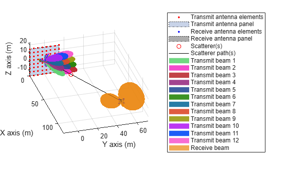
Beam Determination
After the OFDM demodulation, the UE measures the RSRP for all the CSI-RS resources transmitted in different beams, given the current receive beam. Perform these measurements by using the nrCSIRSMeasurements function.
% Perform RSRP measurements
meas = nrCSIRSMeasurements(carrier,csirs,rbfGrid);

% Display the measurement quantities for all CSI-RS resources in dBm
RSRPdBm = max(meas.RSRPPerAntenna,[],1);
disp(['RSRP measurements of all CSI-RS resources (in dBm):' 13 num2str(RSRPdBm)]);
RSRP measurements of all CSI-RS resources (in dBm):
42.3147       33.237      29.1999      45.1102      37.0922      31.4861      39.9414      33.5053      24.5859      17.5821      12.9908      -1.9296
Identify the maximum RSRP value from the measurements and find the best corresponding beam.
% Get the transmit beam index with maximum RSRP value
[~,maxRSRPIdx] = max(RSRPdBm(logical(csirsTransmitted)));

% Get the CSI-RS resource index with maximum RSRP value
[~,maxRSRPResIdx] = max(RSRPdBm);
Calculate the beamwidth which corresponds to the refined transmit beam.
% Get the steering weights corresponding to refined transmit beam
if numBeams == 0
    disp('Refinement has not happened, as NZP-CSI-RS is not transmitted')
else
    refBeamWts = wT(:,maxRSRPIdx);
    csirsAzBeamWidth = beamwidth(txArray,fc,'PropagationSpeed',c,'Weights',refBeamWts,'CutAngle',csirsBeamAng(2,maxRSRPIdx));
    csirsElBeamWidth = beamwidth(txArray,fc,'PropagationSpeed',c,'Weights',refBeamWts,'Cut','Elevation','CutAngle',csirsBeamAng(1,maxRSRPIdx));
    disp(['From initial beam acquisition:' 13 '    Beamwidth of initial SSB beam in azimuth plane is: '...
        num2str(azTxBeamWidth) ' degrees' 13 ...
        '    Beamwidth of initial SSB beam in elevation plane is: '...
        num2str(elTxBeamWidth) ' degrees' 13 13 ...
        'With transmit-end beam refinement:' 13 '    Refined transmit beam ('...
        num2str(maxRSRPIdx) ') corresponds to CSI-RS resource '...
        num2str(maxRSRPResIdx) ' is selected in the direction ['...
        num2str(csirsBeamAng(1,maxRSRPIdx)) ';' num2str(csirsBeamAng(2,maxRSRPIdx))...
        ']' 13 '    Beamwidth of refined transmit beam in azimuth plane is: '...
        num2str(csirsAzBeamWidth) ' degrees' 13 ...
        '    Beamwidth of refined transmit beam in elevation plane is: '...
        num2str(csirsElBeamWidth) ' degrees']);
end
From initial beam acquisition:
    Beamwidth of initial SSB beam in azimuth plane is: 30 degrees
    Beamwidth of initial SSB beam in elevation plane is: 30 degrees

With transmit-end beam refinement:
    Refined transmit beam (4) corresponds to CSI-RS resource 4 is selected in the direction [10;15]
    Beamwidth of refined transmit beam in azimuth plane is: 13.46 degrees
    Beamwidth of refined transmit beam in elevation plane is: 13.24 degrees
Summary and Further Exploration
This example highlights the beam refinement procedure (P-2) using NZP-CSI-RS. The procedure identifies a transmit beam that is finer than the beam from the initial acquisition.
You can configure multiple CSI-RS resources, transmit and receive antenna array configurations, and multiple scatterers to see the variations in the selection of the refined beam. You can also configure the azimuth and elevation angle pairs for the signal transmission and reception.
References
3GPP TR 38.802. "Study on New Radio access technology physical layer aspects." 3rd Generation Partnership Project; Technical Specification Group Radio Access Network.
3GPP TS 38.215. "NR; Physical layer measurements." 3rd Generation Partnership Project; Technical Specification Group Radio Access Network.
3GPP TS 38.214. "NR; Physical layer procedures for data." 3rd Generation Partnership Project; Technical Specification Group Radio Access Network.
Local Functions
function validateCSIRSPorts(csirs)
%   validateCSIRSPorts validates the CSI-RS antenna ports, given the
%   CSI-RS configuration object CSIRS.

    numPorts = csirs.NumCSIRSPorts;
    if any(numPorts > 1)
        error('nr5g:PortsGreaterThan1','CSI-RS resources must be configured for single-port for RSRP measurements.');
    end
end

function csirsTransmitted = getActiveCSIRSRes(carrier,csirs)
%   getActiveCSIRSRes returns a binary vector indicating the presence of
%   all CSI-RS resources in a specified slot, given the carrier
%   configuration object CARRIER and CSI-RS configuration object CSIRS.

    % Extract the following properties of carrier
    NSlotA        = carrier.NSlot;          % Absolute slot number
    NFrameA       = carrier.NFrame;         % Absolute frame number
    SlotsPerFrame = carrier.SlotsPerFrame;  % Number of slots per frame

    % Calculate the appropriate frame number (0...1023) based on the
    % absolute slot number
    NFrameR = mod(NFrameA + fix(NSlotA/SlotsPerFrame),1024);
    % Relative slot number (0...slotsPerFrame-1)
    NSlotR = mod(NSlotA,SlotsPerFrame);

    % Loop over the number of CSI-RS resources
    numCSIRSRes = numel(csirs.CSIRSType);
    csirsTransmitted = zeros(1,numCSIRSRes);
    csirs_struct = validateConfig(csirs);
    for resIdx = 1:numCSIRSRes
        % Extract the CSI-RS slot periodicity and offset
        if isnumeric(csirs_struct.CSIRSPeriod{resIdx})
            Tcsi_rs = csirs_struct.CSIRSPeriod{resIdx}(1);
            Toffset = csirs_struct.CSIRSPeriod{resIdx}(2);
        else
            if strcmpi(csirs_struct.CSIRSPeriod{resIdx},'on')
                Tcsi_rs = 1;
            else
                Tcsi_rs = 0;
            end
            Toffset = 0;
        end

        % Check for the presence of CSI-RS, based on slot periodicity and offset
        if (Tcsi_rs ~= 0) && (mod(SlotsPerFrame*NFrameR + NSlotR - Toffset, Tcsi_rs) == 0)
            csirsTransmitted(resIdx) = 1;
        end
    end
end

function freqRange = validateFc(fc)
%   validateFc validates the carrier frequency FC and returns the frequency
%   range as either 'FR1' or 'FR2'.

    if fc >= 410e6 && fc <= 7.125e9
        freqRange = 'FR1';
    elseif fc >= 24.25e9 && fc <= 52.6e9
        freqRange = 'FR2';
    else
        error('nr5g:invalidFreq',['Selected carrier frequency is outside '...
            'FR1 (410 MHz to 7.125 GHz) and FR2 (24.25 GHz to 52.6 GHz).']);
    end
end

function beamDir = getInitialBeamDir(scatAng,azBeamWidth,elBeamWidth)
%   getInitialBeamDir returns the initial beam direction BEAMDIR, given the
%   angle of scatterer position with respect to transmit or receive antenna
%   array SCATANG, beamwidth of transmit or receive beam in azimuth plane
%   AZBEAMWIDTH, and beamwidth of transmit or receive beam in elevation
%   plane ELBEAMWIDTH.

    % Azimuth angle boundaries of all transmit/receive beams
    azSSBSweep = -180:azBeamWidth:180;
    % Elevation angle boundaries of all transmit/receive beams
    elSSBSweep = -90:elBeamWidth:90;

    % Get the azimuth angle of transmit/receive beam
    azIdx1 = find(azSSBSweep <= scatAng(1),1,'last');
    azIdx2 = find(azSSBSweep >= scatAng(1),1,'first');
    azAng = (azSSBSweep(azIdx1) + azSSBSweep(azIdx2))/2;

    % Get the elevation angle of transmit/receive beam
    elIdx1 = find(elSSBSweep <= scatAng(2),1,'last');
    elIdx2 = find(elSSBSweep >= scatAng(2),1,'first');
    elAng = (elSSBSweep(elIdx1) + elSSBSweep(elIdx2))/2;

    % Form the azimuth and elevation angle pair (in the form of [az;el])
    % for transmit/receive beam
    beamDir = [azAng;elAng];
end