Visualize CDL Channel Model Characteristics
This example shows how to visualize CDL channel characteristics and explore channel information about the antenna element, element pattern, and cluster paths.
Define the channel configuration structure by using an nrCDLChannel System object. Specify the delay profile as CDL-D.
cdl = nrCDLChannel;
cdl.DelayProfile = 'CDL-D';
Configure the transmit array size as a vector of the form , which specifies two rectangular panels (and ) of a 4-by-3 antenna array ( and ) and two polarizations (). The total number of polarized elements in the array is .
txSize = [4 3 2 1 2];
cdl.TransmitAntennaArray.Size = txSize;
Configure the vertical and horizontal element spacing and the vertical and horizontal panel spacing, in wavelength, as a vector of the form . Because panel spacing is measured from the center of the panels, to avoid panel overlapping, set to a value greater than 1 wavelength. To ensure uniform antenna element spacing across vertically and horizontally separated panels, configure panel spacings as and , respectively.
lambda_v = 0.5;
lambda_h = 0.5;
dg_v = lambda_v*txSize(1); % lambda_v * M
dg_h = lambda_h*txSize(2); % lambda_h * N
cdl.TransmitAntennaArray.ElementSpacing = [lambda_v lambda_h dg_v dg_h];
Configure the mechanical orientation of the array as , which specifies 0 degrees bearing, 15 degrees downtilt, and 0 degrees slant.
cdl.TransmitArrayOrientation = [0 15 0]';
For an overview of all other transmit antenna array properties, see the TransmitAntennaArray property of the nrCDLChannel System object.
Display the channel characteristics at the transmitter end.
figTx = displayChannel(cdl,'LinkEnd','Tx');
The generated figure supports customized data tips. Add data tips in the current figure by enabling the data cursor mode.
datacursormode on;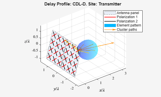
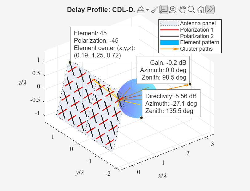
With data cursor mode enabled, explore channel characteristics by adding data tips. To create a data tip, click a data point. To create multiple data tips, press the Shift key while clicking the data points.
For example, this figure shows data tips added to the antenna element, element pattern, and cluster paths at the transmitter end.
Antenna element data tips include information about the position, polarization angle, and element number of each antenna element. The element numbers indicate the order in which the channel model maps input signals column-wise to antenna elements. For more details, see the
TransmitAntennaArray.sizeproperty of thenrCDLChannelSystem object.Element pattern data tips include the directivity corresponding to any azimuth and zenith angles.
Cluster path data tips include the average path gain and azimuth and zenith angles of the cluster path.
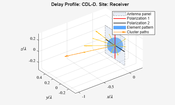
Visualize and explore channel characteristics at the receiver end. To customize the receive antenna array, use the ReceiveAntennaArray property of the nrCDLChannel System object. Then, display the channel characteristics at the receiver end by calling the displayChannel function with the 'LinkEnd','Rx' name-value pair argument.
figRx = displayChannel(cdl,'LinkEnd','Rx');
Explore channel information about the antenna element, element pattern, and cluster paths at the receiver end by enabling data cursor mode for the current figure.
datacursormode on;