Design Microstrip Patch at 77 GHz for Automotive Radar Receiver
This example shows how to create, model, and analyze an inset-fed microstrip patch antenna at high frequencies. As the frequency of operation increases to millimeter waves, the antenna sizes decrease and the antennas are fabricated on printed circuit boards (PCBs). Such printed antennas are of light weight, are inexpensive, easy to integrate, and are widely used as components in a radar. The antenna designed in this example operates at a frequency of 77 GHz and is used in an automotive radar receiver.
Define Parameters
The length and the width of the patch are as provided in [1]. The antenna is designed on a Rogers RO3003™ substrate, with the dielectric constant of 3, loss tangent of 0.0013, and 130 um thickness. A copper conductor of thickness 17 um is used as the patch.
PL = 1049e-6;
PW = 1412e-6;
sub = dielectric(Name="RO3003",EpsilonR=3,LossTangent=0.0013,Thickness=130e-6);
con = metal(Name="Copper",Conductivity=5.96e7,Thickness=17e-6);
Create Microstrip Patch Antenna
Create an inset-fed microstrip patch antenna using the patchMicrostripInsetfed object. The ground plane dimensions are 1800 um-by-2800 um. The length and the width of the notch are specified as 100 um and 160 um, respectively. The strip line width is 100 um. The antenna feed is located at the end of the strip.
ant = patchMicrostripInsetfed(Length=PL,Width=PW,Height=sub.Thickness,...
    Substrate=sub,Conductor=con,GroundPlaneLength=1800e-6,...
    GroundPlaneWidth=2800e-6,NotchLength=100e-6,NotchWidth=160e-6,...
    StripLineWidth=100e-6,FeedOffset=[-900e-6 0]);
show(ant)
title("Inset-fed Microstrip Patch Antenna")

Analyze Antenna
Use the mesh function to create and display the mesh structure of the patch microstrip antenna. Mesh the antenna with a maximum edge length of 140e-6 m.
mesh(ant,MaxEdgeLength=140e-6)
Warning: An error occurred while drawing the scene: GraphicsView error in command: interactionsmanagermessage:  TypeError: Cannot read properties of null (reading '_gview')
    at new g (https://127.0.0.1:31515/toolbox/matlab/uitools/figurelibjs/release/bundle.mwBundle.gbtfigure-lib.js?mre=https
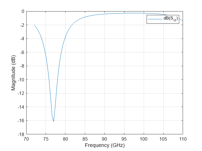
Use the sparameters function to plot the S-parameters of the patch antenna over a frequency range of 72-110 GHz. The antenna resonates at 77 GHz, with an approximate bandwidth of 2.7 GHz.
sf = sparameters(ant,linspace(72e9,110e9,100));
figure
rfplot(sf)
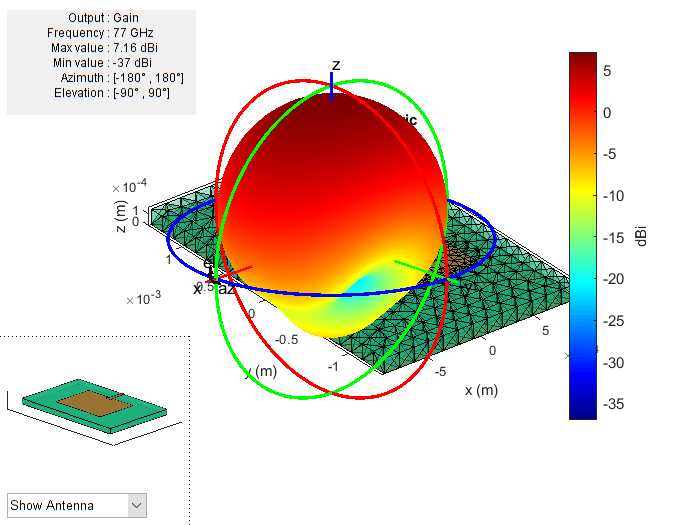
Use the pattern function to plot the 3-D radiation pattern of the antenna at 77 GHz. The gain obtained from the antenna is over 7 dBi.
pattern(ant,77e9)
Warning: An error occurred while drawing the scene: GraphicsView error in command: interactionsmanagermessage:  TypeError: Cannot read properties of null (reading '_gview')
    at new g (https://127.0.0.1:31515/toolbox/matlab/uitools/figurelibjs/release/bundle.mwBundle.gbtfigure-lib.js?mre=https
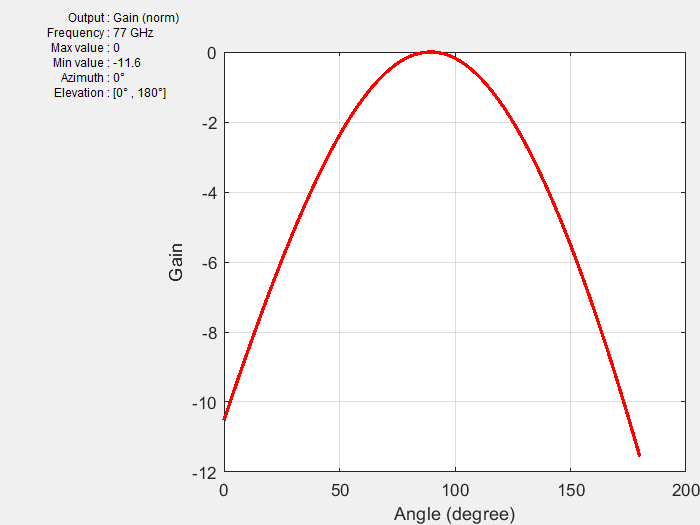
Plot the copolarization plot in the H-plane for the antenna at 77 GHz in a rectangular coordinate system with normalization.
pattern(ant,77e9,0,0:1:180,CoordinateSystem="rectangular",Normalize=true)
Conclusion
The analysis results of the 77 GHz microstrip patch antenna show that it has good bandwidth and gain and is suitable for use in applications like automotive radar receivers.
References
[1] Seyyedesfahlan, Mehdi and I. Tekin. “77 GHz PCB Patch Antenna.” URSI (International Union of Radio Science) Türkiye Ulusal Komitesi (2016).