Port Analysis
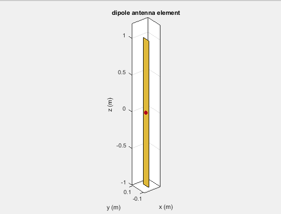
The port of an antenna is the physical location where the RF source is connected. From a network theory perspective, the antenna has a single port. In Antenna Toolbox™, a red dot on the antenna figure represents the feed point. A half-wavelength dipole is shown with its feed point:
All antennas are excited by a phasor voltage of 1V with a
0 deg phase angle at the port. The various terminal port
parameters are as follows:
Input Impedance
Input impedance is the ratio of voltage to current at the
port. Antenna impedance is calculated as the ratio of the phasor voltage, which is
1V at a phase angle of 0 deg, to the
phasor current at the port. The impedance equation is:
where:
Vis the antenna excitation voltageIis the currentRis the antenna resistance in ohmsXis the antenna reactance in ohms
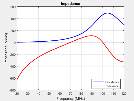
Antenna input impedance is a frequency-dependent quantity. The plot shows the input impedance of a dipole antenna over the frequency band 20–120 MHz. The resistance and reactance traces vary with frequency. The variation can be qualitatively described in terms of resonances.
d = dipole;
impedance(d,20e6:1e6:120e6)
Use impedance to calculate the input
impedance of any antennas in Antenna Toolbox.
Resonance
The resonant frequency of the antenna is the frequency at which the reactance of the antenna is equal to zero.
The plot shows two resonance points of a dipole antenna.
d = dipole;
resonantFrequency(d,20e6:1e6:120e6)
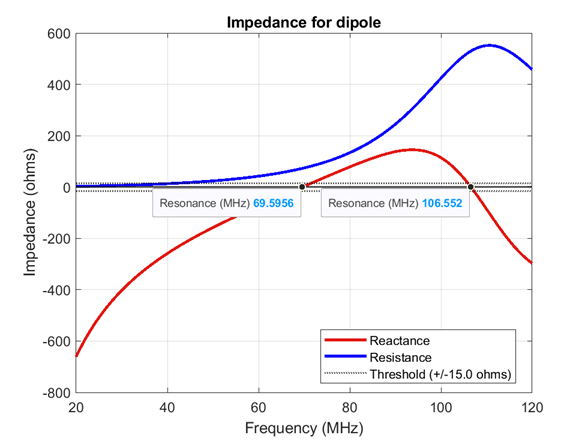
In the plot, the reactance values are negative, or capacitive, before the resonance. These values are positive or inductive after the resonance. This type of resonance is called series resonance. You can model this type of resonance using a series RLC circuit. If the impedance curve goes from positive reactance to negative reactance, it is called parallel resonance. You can model this type of resonance using a parallel RLC circuit.
Use resonantFrequency to calculate the resonant frequency of the
antennas in Antenna Toolbox.
Reflection Coefficient
The reflection coefficient, or
S11, of the antenna describes a
relative fraction of the incident RF power that is reflected back due to the
impedance mismatch. Impedance mismatch is the difference between the input impedance
of the antenna and the characteristic impedance of the transmission line (or the
generator impedance when the transmission line is not present). The characteristic
impedance is the reference impedance.
S = sparameters(d,20e6:1e6:120e6,72)
rfplot(S)
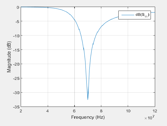
The reflection coefficient also gives the operating bandwidth of the antenna. Antenna bandwidth is usually the frequency band over which the magnitude of the reflection coefficient is below -10 dB.
Use sparameters to calculate the value of
S11 for any antenna in the
Antenna Toolbox.
Return Loss
The return loss of an antenna is a measure of the effectiveness of power delivery from a transmission line or coaxial cable to a load such as an antenna. The return loss can also be defined as the difference in dB between the power sent toward the antenna and the power reflected back from it. The higher the power ratio, the better matching between load and line. Return loss equation is:
where:
RLis the return lossS11is the reflection coefficient, or power reflected from the antenna.
For passive devices, the return loss is a positive non-dissipative term representing the reduction in amplitude of the reflected wave in comparison to the incident wave. In active devices, a negative return loss is possible.
d = dipole;
returnLoss(d,20e6:1e6:120e6,72)
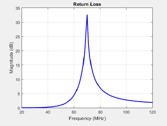
Return loss plots also give the operating bandwidth of the antenna. Antenna
bandwidth is the frequency band over which the magnitude of return loss is greater
than 10 dB. Use the returnLoss function to calculate the
return loss of any antenna in the antenna catalog.
Voltage Standing Wave Ratio
The voltage standing wave ratio (VSWR) of an antenna is another measure of impedance matching between transmission line and antenna. The standing wave is generated because of the impedance mismatch at the port. VSWR equation is:
where:
S11is the reflection coefficient.
d = dipole;
vswr(d,20e6:1e6:120e6,72)
axis([20 120 1 20])
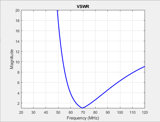
VSWR is scalar and contains no phase information. The value of
VSWR lies between 1 and infinity. Antenna bandwidth is usually
the frequency band over which the VSWR is less than approximately 2.
Use vswr to calculate the voltage
standing wave ratio for any antenna in Antenna Toolbox.
Efficiency
The Efficiency of an antenna, also known as radiation
efficiency, quantifies the effectiveness of an antenna in delivering its output with
minimal losses. It is defined as the ratio of the power radiated
Prad by the antenna to the power
supplied Pin to the antenna. It is usually
expressed as a percentage value.
d = dipole(Conductor=metal("Iron"));
efficiency(d,20e6:1e6:120e6)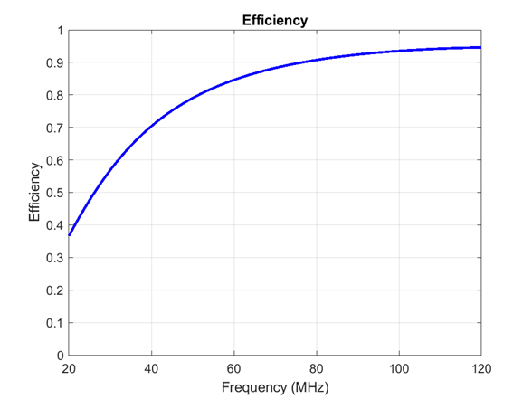
Use efficiency to calculate the radiation efficiency of the antennas in
Antenna Toolbox.
Bandwidth
Bandwidth describes the range of frequencies over which the antenna can properly radiate or receive energy. It is a fundamental antenna parameter. Often, the desired bandwidth is one of the parameters used to determine which antenna to use. Antenna bandwidth is usually the frequency band over which the magnitude of the reflection coefficient is below -10 dB, or the magnitude of the return loss is greater than 10 dB, or the VSWR is less than approximately 2. All these criteria are equivalent. You can control the bandwidth using proper antenna design.
d = dipole;
bandwidth(dipole,20e6:1e6:120e6)
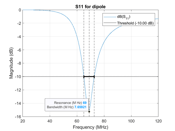
Use bandwidth to calculate the bandwidth of the antennas in Antenna Toolbox.
References
[1] Balanis, C.A. Antenna Theory: Analysis and Design.3rd Ed. New York: Wiley, 2005.
[2] Stutzman, Warren L., and Thiele, Gary A. Antenna Theory and Design. 3rd Ed. New York: Wiley, 2013.
[3] Bird, T.S. “Definition and Misuse of Return Loss.” IEEE Antennas and Propagation Magazine. Vol. 51, Issue 2, April 2009, pp. 166–167.