Impulse Response Measurer
Measure impulse response of audio system
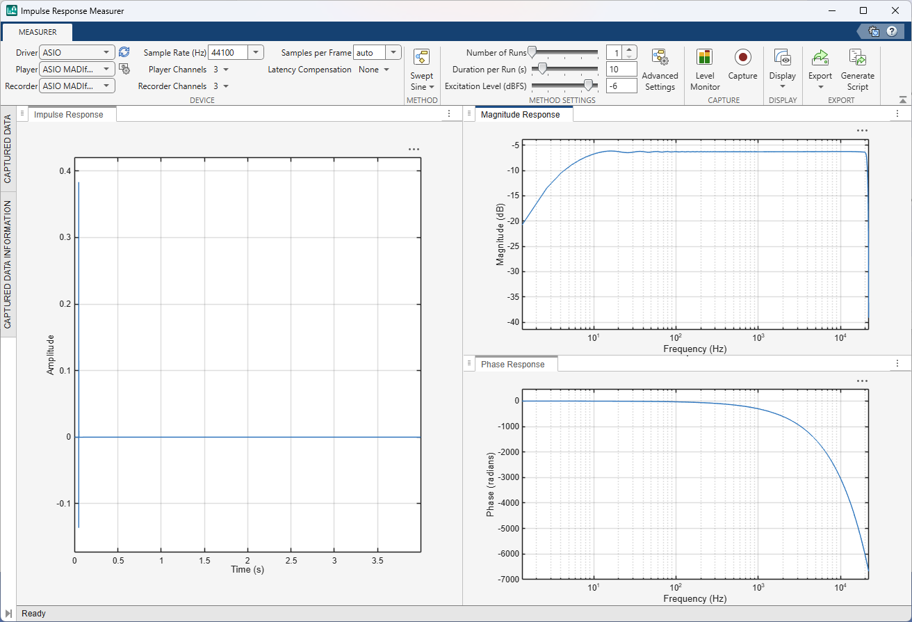
Description
The Impulse Response Measurer app enables you to acquire, analyze, and export impulse response and frequency response measurements through a user interface.
Using this app, you can:
Acquire impulse responses from one or more input channels to create filters and generate models for offline simulations.
Select drivers, with Windows™ support for ASIO™, DirectSound, and WASAPI drivers.
Specify different devices for playback and recording (when sample rates are compatible).
Determine whether audio devices (loudspeakers, for example) meet time and frequency specifications.
Optimize audio systems, such as automotive-acoustic systems, to match goal specifications.
Acquire accurate impulse response measurements for use in acoustic reporting.
Generate MATLAB® scripts that perform the same measurements in your workspace.
Open the Impulse Response Measurer App
MATLAB Toolstrip: On the Apps tab, under Signal Processing and Audio, click the app icon.
MATLAB Command prompt: Enter impulseResponseMeasurer.
Examples
For large systems with multiple audio devices and multiple input and output channels, tracking how reported devices and channels correspond to physical devices can be difficult. The Impulse Response Measurer provides a level monitor so that you can verify your audio I/O configuration.
To open the level monitor, click Level Monitor, ![]() .
.

In the Device section of the toolstrip, choose the driver, the player and recorder devices, and player and recorder channels. Choose the test signal and the test audio level in the level monitor. Verify that the level reported by the recorder reacts appropriately to level changes output by the player. Once you are satisfied that your system is configured correctly, close the level monitor and begin the impulse response capture.
Related Examples
Parameters
References
[1] Farina, Angelo. "Advancements in Impulse Response Measurements by Sine Sweeps." Presented at the Audio Engineering Society 122nd Convention, Vienna, Austria, 2007.
[2] Guy-Bart, Stan, Jean-Jacques Embrachts, and Dominique Archambeau. "Comparison of Different Impulse Response Measurement Techniques." Journal of Audio Engineering Society. Vol. 50, Issue 4, 2002, pp. 246–262.
[3] Armelloni, Enrico, Christian Giottoli, and Angelo Farina. "Implementation of Real-Time Partitioned Convolution on a DSP Board." Application of Signal Processing to Audio and Acoustics, 2003 IEEE Workshop, pp. 71–74. IEEE, 2003.