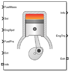
CI Core Engine
Compression-ignition engine from intake to exhaust port
Libraries:
Powertrain Blockset /
Propulsion /
Combustion Engine Components /
Core Engine
Description
The CI Core Engine block implements a compression-ignition (CI) engine from intake to the exhaust port. You can use the block for hardware-in-the-loop (HIL) engine control design or vehicle-level fuel economy and performance simulations.
The CI Core Engine block calculates:
Brake torque
Exhaust temperature
Air-fuel ratio (AFR)
Fuel rail pressure
Engine-out (EO) exhaust emissions:
Hydrocarbon (HC)
Carbon monoxide (CO)
Nitric oxide and nitrogen dioxide (NOx)
Carbon dioxide (CO2)
Particulate matter (PM)
Air Mass Flow
To calculate the air mass flow, the compression-ignition (CI) engine uses the CI Engine Speed-Density Air Mass Flow Model. The speed-density model uses the speed-density equation to calculate the engine air mass flow, relating the engine intake port mass flow to the intake manifold pressure, intake manifold temperature, and engine speed.
Brake Torque
To calculate the engine torque, you can configure the block to use either of these torque models.
| Brake Torque Model | Description |
|---|---|
| CI Engine Torque Structure Model |
The CI core engine torque structure model determines the engine torque by reducing the maximum engine torque potential as these engine conditions vary from nominal:
To account for the effect of post-inject fuel on torque, the model uses a calibrated torque offset table. |
| CI Engine Simple Torque Model | For the simple engine torque calculation, the CI engine uses a torque lookup table map that is a function of engine speed and injected fuel mass. |
Fuel Flow
In the CI Core Engine and CI Controller blocks, you can represent multiple injections with the start of injection (SOI) and fuel mass inputs to the model. To specify the type of injection, use the Fuel mass injection type identifier parameter.
| Type of Injection | Parameter Value |
|---|---|
Pilot |
|
Main |
|
Post |
|
Passed |
|
The model considers Passed fuel injections and fuel injected
later than a threshold to be unburned fuel. Use the Maximum start of injection angle
for burned fuel, f_tqs_f_burned_soi_limit parameter to specify the
threshold.
To calculate the engine fuel mass flow, the CI Core Engine block uses fuel mass flow delivered by the injectors and the engine airflow.
To calculate the fuel economy for high-fidelity models, the block uses the volumetric fuel flow.
The equation uses these variables.
| Fuel mass flow, g/s | |
| mfuel,inj | Fuel mass per injection |
Crankshaft revolutions per power stroke, rev/stroke | |
Number of engine cylinders | |
| N | Engine speed, rpm |
| Qfuel | Volumetric fuel flow |
| Sgfuel | Specific gravity of fuel |
The block uses the internal signal FlwDir to track the direction of the flow.
Air-Fuel Ratio
To calculate the air-fuel (AFR) ratio, the CI Core Engine and SI Core Engine blocks implement this equation.
The CI Core Engine uses this equation to calculate the relative AFR.
To calculate the exhaust gas recirculation (EGR), the blocks implement this equation. The calculation expresses the EGR as a percent of the total intake port flow.
The equations use these variables.
Air-fuel ratio | |
| AFRs | Stoichiometric air-fuel ratio |
Engine air mass flow | |
Fuel mass flow | |
λ | Relative AFR |
| yintk,b | Intake burned mass fraction |
| EGRpct | EGR percent |
Recirculated burned gas mass flow rate |
Exhaust Temperature
The exhaust temperature calculation depends on the torque model. For both torque models, the block implements lookup tables.
Torque Model | Description | Equations |
|---|---|---|
| Exhaust temperature lookup table is a function of the injected fuel mass and engine speed. |
|
Torque Structure |
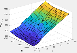
The nominal exhaust temperature, Texhnom, is a product of these exhaust temperature efficiencies:
The exhaust temperature, Texhnom, is offset by a post temperature effect, ΔTpost, that accounts for post and late injections during the expansion and exhaust strokes. |
|
The equations use these variables.
F | Compression stroke injected fuel mass |
N | Engine speed |
Texh | Exhaust manifold gas temperature |
Texhopt | Optimal exhaust manifold gas temperature |
| ΔTpost | Post injection temperature effect |
| Texhnom | Nominal exhaust temperature |
SOIexhteff | Main SOI exhaust temperature efficiency multiplier |
ΔSOI | Main SOI timing relative to optimal timing |
MAPexheff | Intake manifold gas pressure exhaust temperature efficiency multiplier |
MAPratio | Intake manifold gas pressure ratio relative to optimal pressure ratio |
λ | Intake manifold gas lambda |
MATexheff | Intake manifold gas temperature exhaust temperature efficiency multiplier |
ΔMAT | Intake manifold gas temperature relative to optimal temperature |
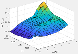
O2Pexheff | Intake manifold gas oxygen exhaust temperature efficiency multiplier |
ΔO2P | Intake gas oxygen percent relative to optimal |
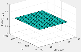
FUELPexheff | Fuel rail pressure exhaust temperature efficiency multiplier |
ΔFUELP | Fuel rail pressure relative to optimal |
EO Exhaust Emissions
The block calculates these engine-out (EO) exhaust emissions:
Hydrocarbon (HC)
Carbon monoxide (CO)
Nitric oxide and nitrogen dioxide (NOx)
Carbon dioxide (CO2)
Particulate matter (PM)
The exhaust temperature determines the specific enthalpy.
The exhaust mass flow rate is the sum of the intake port air mass flow and the fuel mass flow.
To calculate the exhaust emissions, the block multiplies the emission mass fraction by the exhaust mass flow rate. To determine the emission mass fractions, the block uses lookup tables that are functions of the engine torque and speed.
The fraction of air and fuel entering the intake port, injected fuel, and stoichiometric AFR determine the air mass fraction that exits the exhaust.
If the engine is operating at the stoichiometric or fuel rich AFR, no air exits the exhaust. Unburned hydrocarbons and burned gas comprise the remainder of the exhaust gas. This equation determines the exhaust burned gas mass fraction.
The equations use these variables.
Engine exhaust temperature | |
Exhaust manifold inlet-specific enthalpy | |
Exhaust gas specific heat | |
Intake port air mass flow rate | |
Fuel mass flow rate | |
Exhaust mass flow rate | |
Intake fuel mass fraction | |
| yexh,i | Exhaust mass fraction for i = CO2, CO, HC, NOx, air, burned gas, and PM |
Exhaust mass flow rate for i = CO2, CO, HC, NOx, air, burned gas, and PM | |
| Tbrake | Engine brake torque |
| N | Engine speed |
| yexh,air | Exhaust air mass fraction |
| yexh,b | Exhaust air burned mass fraction |
Power Accounting
For the power accounting, the block implements equations that depend on Torque model.
When you set Torque model to Simple Torque Lookup, the block implements these equations.
| Bus Signal | Description | Equations | ||
|---|---|---|---|---|
|
|
| Intake heat flow | |
PwrExhHeatFlw | Exhaust heat flow | |||
PwrCrkshft | Crankshaft power | |||
| PwrFuel | Fuel input power | ||
PwrLoss | All losses | |||
| Not used | |||
When you set Torque model to Torque Structure, the block implements these equations.
| Bus Signal | Description | Equations | ||
|---|---|---|---|---|
|
|
| Intake heat flow | |
PwrExhHeatFlw | Exhaust heat flow | |||
PwrCrkshft | Crankshaft power | |||
| PwrFuel | Fuel input power | ||
PwrFricLoss | Friction loss | |||
PwrPumpLoss | Pumping loss | |||
PwrHeatTrnsfrLoss | Heat transfer loss | |||
| Not used | |||
| hexh | Exhaust manifold inlet-specific enthalpy |
| hintk | Intake port specific enthalpy |
Intake port air mass flow rate | |
Fuel mass flow rate | |
Exhaust mass flow rate | |
| ω | Engine speed |
| Tbrake | Brake torque |
| Tpump | Engine pumping work offset to inner torque |
| Tfric | Engine friction torque |
| LHV | Fuel lower heating value |
Examples

Build Conventional Vehicle Model
Build a vehicle with an internal combustion engine using the conventional vehicle reference application.
Calibrate, Validate, and Optimize CI Engine with Dynamometer Test Harness
Simulate a compression-ignition (CI) engine and controller under a dynamometer test harness using the CI engine dynamometer reference application.
Ports
Input
Output
Parameters
Block Options
To calculate the engine torque, you can configure the block to use either of these torque models.
| Brake Torque Model | Description |
|---|---|
| CI Engine Torque Structure Model |
The CI core engine torque structure model determines the engine torque by reducing the maximum engine torque potential as these engine conditions vary from nominal:
To account for the effect of post-inject fuel on torque, the model uses a calibrated torque offset table. |
| CI Engine Simple Torque Model | For the simple engine torque calculation, the CI engine uses a torque lookup table map that is a function of engine speed and injected fuel mass. |
Programmatic Use
To set the block parameter value programmatically, use
the set_param function.
To get the block parameter value
programmatically, use the get_param function.
| Parameter: | TrqOptionPopup |
| Values: | Torque
Structure (default) | Simple Torque Lookup |
| Data Types: | character vector |
Air
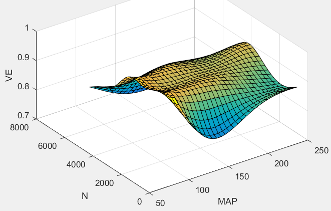
The volumetric efficiency lookup table is a function of the intake manifold absolute pressure at intake valve closing (IVC) and engine speed
where:
is engine volumetric efficiency, dimensionless.
MAP is intake manifold absolute pressure, in KPa.
N is engine speed, in rpm.
Programmatic Use
To set the block parameter value programmatically, use
the set_param function.
To get the block parameter value
programmatically, use the get_param function.
| Parameter: | f_nv |
| Values: | array |
| Data Types: | double |
Intake manifold pressure breakpoints for speed-density volumetric efficiency lookup table, in KPa.
Programmatic Use
To set the block parameter value programmatically, use
the set_param function.
To get the block parameter value
programmatically, use the get_param function.
| Parameter: | f_nv_prs_bpt |
| Values: | vector |
| Data Types: | double |
Engine speed breakpoints for speed-density volumetric efficiency lookup table, in rpm.
Programmatic Use
To set the block parameter value programmatically, use
the set_param function.
To get the block parameter value
programmatically, use the get_param function.
| Parameter: | f_nv_n_bpt |
| Values: | vector |
| Data Types: | double |
Torque
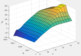
Torque - Simple Torque Lookup
For the simple torque lookup table model, the CI engine uses a lookup table is a function of engine speed and injected fuel mass, , where:
Tq = Tbrake is engine brake torque after accounting for engine mechanical and pumping friction effects, in N·m.
F is injected fuel mass, in mg per injection.
N is engine speed, in rpm.
Programmatic Use
To set the block parameter value programmatically, use
the set_param function.
To get the block parameter value
programmatically, use the get_param function.
| Parameter: | f_tq_nf |
| Values: | array |
| Data Types: | double |
Dependencies
To enable this parameter, for Torque model, select
Simple Torque Lookup.
Torque - Torque Structure
Engine speed breakpoints, in rpm.
Programmatic Use
To set the block parameter value programmatically, use
the set_param function.
To get the block parameter value
programmatically, use the get_param function.
| Parameter: | f_tqs_n_bpt |
| Values: | vector |
| Data Types: | double |
Dependencies
To enable this parameter, for Torque model, select
Torque Structure.
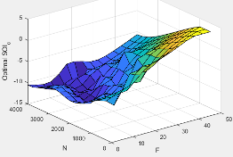
The optimal main start of injection (SOI) timing lookup table, ƒSOIc, is a function of the engine speed and injected fuel mass, SOIc = ƒSOIc(F,N), where:
SOIc is optimal SOI timing, in degATDC.
F is compression stroke injected fuel mass, in mg per injection.
N is engine speed, in rpm.
Programmatic Use
To set the block parameter value programmatically, use
the set_param function.
To get the block parameter value
programmatically, use the get_param function.
| Parameter: | f_tqs_mainsoi |
| Values: | array |
| Data Types: | double |
Dependencies
To enable this parameter, for Torque model, select
Torque Structure.
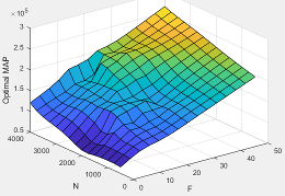
The optimal intake manifold gas pressure lookup table, ƒMAP, is a function of the engine speed and injected fuel mass, MAP = ƒMAP(F,N), where:
MAP is optimal intake manifold gas pressure, in Pa.
F is compression stroke injected fuel mass, in mg per injection.
N is engine speed, in rpm.
Programmatic Use
To set the block parameter value programmatically, use
the set_param function.
To get the block parameter value
programmatically, use the get_param function.
| Parameter: | f_tqs_map |
| Values: | array |
| Data Types: | double |
Dependencies
To enable this parameter, for Torque model, select
Torque Structure.
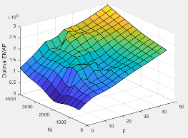
The optimal exhaust manifold gas pressure lookup table, ƒEMAP, is a function of the engine speed and injected fuel mass, EMAP = ƒEMAP(F,N), where:
EMAP is optimal exhaust manifold gas pressure, in Pa.
F is compression stroke injected fuel mass, in mg per injection.
N is engine speed, in rpm.
Programmatic Use
To set the block parameter value programmatically, use
the set_param function.
To get the block parameter value
programmatically, use the get_param function.
| Parameter: | f_tqs_emap |
| Values: | array |
| Data Types: | double |
Dependencies
To enable this parameter, for Torque model, select
Torque Structure.
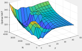
The optimal intake manifold gas temperature lookup table, ƒMAT, is a function of the engine speed and injected fuel mass, MAT = ƒMAT(F,N), where:
MAT is optimal intake manifold gas temperature, in K.
F is compression stroke injected fuel mass, in mg per injection.
N is engine speed, in rpm.
Programmatic Use
To set the block parameter value programmatically, use
the set_param function.
To get the block parameter value
programmatically, use the get_param function.
| Parameter: | f_tqs_mat |
| Values: | array |
| Data Types: | double |
Dependencies
To enable this parameter, for Torque model, select
Torque Structure.
The optimal intake gas oxygen percent lookup table, ƒO2, is a function of the engine speed and injected fuel mass, O2PCT = ƒO2(F,N), where:
O2PCT is optimal intake gas oxygen, in percent.
F is compression stroke injected fuel mass, in mg per injection.
N is engine speed, in rpm.
Programmatic Use
To set the block parameter value programmatically, use
the set_param function.
To get the block parameter value
programmatically, use the get_param function.
| Parameter: | f_tqs_o2pct |
| Values: | array |
| Data Types: | double |
Dependencies
To enable this parameter, for Torque model, select
Torque Structure.
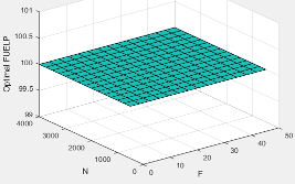
The optimal fuel rail pressure lookup table, ƒfuelp, is a function of the engine speed and injected fuel mass, FUELP = ƒfuelp(F,N), where:
FUELP is optimal fuel rail pressure, in MPa.
F is compression stroke injected fuel mass, in mg per injection.
N is engine speed, in rpm.
Programmatic Use
To set the block parameter value programmatically, use
the set_param function.
To get the block parameter value
programmatically, use the get_param function.
| Parameter: | f_tqs_fuelpress |
| Values: | array |
| Data Types: | double |
Dependencies
To enable this parameter, for Torque model, select
Torque Structure.
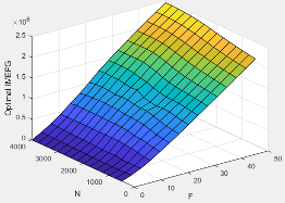
The optimal gross indicated mean effective pressure lookup table, ƒimepg, is a function of the engine speed and injected fuel mass, IMEPG = ƒimepg(F,N), where:
IMEPG is optimal gross indicated mean effective pressure, in Pa.
F is compression stroke injected fuel mass, in mg per injection.
N is engine speed, in rpm.
Programmatic Use
To set the block parameter value programmatically, use
the set_param function.
To get the block parameter value
programmatically, use the get_param function.
| Parameter: | f_tqs_imepg |
| Values: | array |
| Data Types: | double |
Dependencies
To enable this parameter, for Torque model, select
Torque Structure.
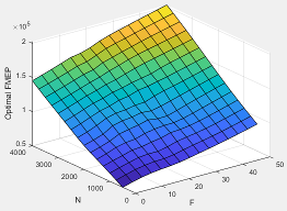
The optimal friction mean effective pressure lookup table, ƒfmep, is a function of the engine speed and injected fuel mass, FMEP = ƒfmep(F,N), where:
FMEP is optimal friction mean effective pressure, in Pa.
F is compression stroke injected fuel mass, in mg per injection.
N is engine speed, in rpm.
Programmatic Use
To set the block parameter value programmatically, use
the set_param function.
To get the block parameter value
programmatically, use the get_param function.
| Parameter: | f_tqs_fmep |
| Values: | array |
| Data Types: | double |
Dependencies
To enable this parameter, for Torque model, select
Torque Structure.
The optimal pumping mean effective pressure lookup table, ƒpmep, is a function of the engine speed and injected fuel mass, PMEP = ƒpmep(F,N), where:
PMEP is optimal pumping mean effective pressure, in Pa.
F is compression stroke injected fuel mass, in mg per injection.
N is engine speed, in rpm.
Programmatic Use
To set the block parameter value programmatically, use
the set_param function.
To get the block parameter value
programmatically, use the get_param function.
| Parameter: | f_tqs_pmep |
| Values: | array |
| Data Types: | double |
Dependencies
To enable this parameter, for Torque model, select
Torque Structure.
Friction multiplier as a function of temperature, dimensionless.
Programmatic Use
To set the block parameter value programmatically, use
the set_param function.
To get the block parameter value
programmatically, use the get_param function.
| Parameter: | f_tqs_fric_temp_mod |
| Values: | array |
| Data Types: | double |
Dependencies
To enable this parameter, for Torque model, select
Torque Structure.
Friction multiplier temperature breakpoints, in K.
Programmatic Use
To set the block parameter value programmatically, use
the set_param function.
To get the block parameter value
programmatically, use the get_param function.
| Parameter: | f_tqs_fric_temp_bpt |
| Values: | vector |
| Data Types: | double |
Dependencies
To enable this parameter, for Torque model, select
Torque Structure.
The main start of injection (SOI) timing efficiency multiplier lookup table, ƒSOIeff, is a function of the engine speed and main SOI timing relative to optimal timing, SOIeff = ƒSOIeff(ΔSOI,N), where:
SOIeff is main SOI timing efficiency multiplier, dimensionless.
ΔSOI is main SOI timing relative to optimal timing, in degBTDC.
N is engine speed, in rpm.
Programmatic Use
To set the block parameter value programmatically, use
the set_param function.
To get the block parameter value
programmatically, use the get_param function.
| Parameter: | f_tqs_mainsoi_eff |
| Values: | array |
| Data Types: | double |
Dependencies
To enable this parameter, for Torque model, select
Torque Structure.
Main start of injection timing relative to optimal timing breakpoints, in degBTDC.
Programmatic Use
To set the block parameter value programmatically, use
the set_param function.
To get the block parameter value
programmatically, use the get_param function.
| Parameter: | f_tqs_mainsoi_delta_bpt |
| Values: | vector |
| Data Types: | double |
Dependencies
To enable this parameter, for Torque model, select
Torque Structure.
The intake manifold gas pressure efficiency multiplier lookup table, ƒMAPeff, is a function of the intake manifold gas pressure ratio relative to optimal pressure ratio and lambda, MAPeff = ƒMAPeff(MAPratio,λ), where:
MAPeff is intake manifold gas pressure efficiency multiplier, dimensionless.
MAPratio is intake manifold gas pressure ratio relative to optimal pressure ratio, dimensionless.
λ is intake manifold gas lambda, dimensionless.
Programmatic Use
To set the block parameter value programmatically, use
the set_param function.
To get the block parameter value
programmatically, use the get_param function.
| Parameter: | f_tqs_map_eff |
| Values: | array |
| Data Types: | double |
Dependencies
To enable this parameter, for Torque model, select
Torque Structure.
Intake manifold gas pressure ratio relative to optimal pressure ratio breakpoints, dimensionless.
Programmatic Use
To set the block parameter value programmatically, use
the set_param function.
To get the block parameter value
programmatically, use the get_param function.
| Parameter: | f_tqs_map_ratio_bpt |
| Values: | vector |
| Data Types: | double |
Dependencies
To enable this parameter, for Torque model, select
Torque Structure.
Intake manifold gas lambda breakpoints, dimensionless.
Programmatic Use
To set the block parameter value programmatically, use
the set_param function.
To get the block parameter value
programmatically, use the get_param function.
| Parameter: | f_tqs_lambda_bpt |
| Values: | vector |
| Data Types: | double |
Dependencies
To enable this parameter, for Torque model, select
Torque Structure.
The intake manifold gas temperature efficiency multiplier lookup table, ƒMATeff, is a function of the engine speed and intake manifold gas temperature relative to optimal temperature, MATeff = ƒMATeff(ΔMAT,N), where:
MATeff is intake manifold gas temperature efficiency multiplier, dimensionless.
ΔMAT is intake manifold gas temperature relative to optimal temperature, in K.
N is engine speed, in rpm.
Programmatic Use
To set the block parameter value programmatically, use
the set_param function.
To get the block parameter value
programmatically, use the get_param function.
| Parameter: | f_tqs_mat_eff |
| Values: | array |
| Data Types: | double |
Dependencies
To enable this parameter, for Torque model, select
Torque Structure.
Intake manifold gas temperature relative to optimal gas temperature breakpoints, in K.
Programmatic Use
To set the block parameter value programmatically, use
the set_param function.
To get the block parameter value
programmatically, use the get_param function.
| Parameter: | f_tqs_mat_delta_bpt |
| Values: | vector |
| Data Types: | double |
Dependencies
To enable this parameter, for Torque model, select
Torque Structure.
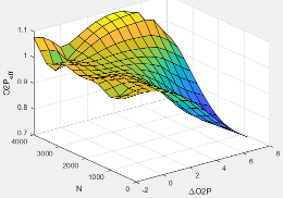
The intake manifold gas oxygen efficiency multiplier lookup table, ƒO2Peff, is a function of the engine speed and intake manifold gas oxygen percent relative to optimal, O2Peff = ƒO2Peff(ΔO2P,N), where:
O2Peff is intake manifold gas oxygen efficiency multiplier, dimensionless.
ΔO2P is intake gas oxygen percent relative to optimal, in percent.
N is engine speed, in rpm.
Programmatic Use
To set the block parameter value programmatically, use
the set_param function.
To get the block parameter value
programmatically, use the get_param function.
| Parameter: | f_tqs_o2pct_eff |
| Values: | array |
| Data Types: | double |
Dependencies
To enable this parameter, for Torque model, select
Torque Structure.
Intake gas oxygen percent relative to optimal breakpoints, in percent.
Programmatic Use
To set the block parameter value programmatically, use
the set_param function.
To get the block parameter value
programmatically, use the get_param function.
| Parameter: | f_tqs_o2pct_delta_bpt |
| Values: | vector |
| Data Types: | double |
Dependencies
To enable this parameter, for Torque model, select
Torque Structure.
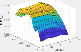
The fuel rail pressure efficiency multiplier lookup table, ƒFUELPeff, is a function of the engine speed and fuel rail pressure relative to optimal breakpoints, FUELPeff = ƒFUELPeff(ΔFUELP,N), where:
FUELPeff is fuel rail pressure efficiency multiplier, dimensionless.
ΔFUELP is fuel rail pressure relative to optimal, in MPa.
N is engine speed, in rpm.
Programmatic Use
To set the block parameter value programmatically, use
the set_param function.
To get the block parameter value
programmatically, use the get_param function.
| Parameter: | f_tqs_fuelpress_eff |
| Values: | array |
| Data Types: | double |
Dependencies
To enable this parameter, for Torque model, select
Torque Structure.
Fuel rail pressure relative to optimal breakpoints, in MPa.
Programmatic Use
To set the block parameter value programmatically, use
the set_param function.
To get the block parameter value
programmatically, use the get_param function.
| Parameter: | f_tqs_fuelpress_delta_bpt |
| Values: | vector |
| Data Types: | double |
Dependencies
To enable this parameter, for Torque model, select
Torque Structure.
Fuel mass injection type identifier, dimensionless.
In the CI Core Engine and CI Controller blocks, you can represent multiple injections with the start of injection (SOI) and fuel mass inputs to the model. To specify the type of injection, use the Fuel mass injection type identifier parameter.
| Type of Injection | Parameter Value |
|---|---|
Pilot |
|
Main |
|
Post |
|
Passed |
|
The model considers Passed fuel injections and fuel injected
later than a threshold to be unburned fuel. Use the Maximum start of injection angle
for burned fuel, f_tqs_f_burned_soi_limit parameter to specify the
threshold.
Programmatic Use
To set the block parameter value programmatically, use
the set_param function.
To get the block parameter value
programmatically, use the get_param function.
| Parameter: | f_tqs_f_inj_type |
| Values: | 0 (default) | scalar |
| Data Types: | double |
Dependencies
To enable this parameter, for Torque model, select
Torque Structure.
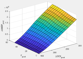
The indicated mean effective pressure post inject correction lookup table, ƒIMEPpost, is a function of the engine speed and fuel rail pressure relative to optimal breakpoints, ΔIMEPpost = ƒIMEPpost(ΔSOIpost,Fpost), where:
ΔIMEPpost is indicated mean effective pressure post inject correction, in Pa.
ΔSOIpost is indicated mean effective pressure post inject start of inject timing centroid, in degATDC.
Fpost is indicated mean effective pressure post inject mass sum, in mg per injection.
Programmatic Use
To set the block parameter value programmatically, use
the set_param function.
To get the block parameter value
programmatically, use the get_param function.
| Parameter: | f_tqs_imep_post_corr |
| Values: | array |
| Data Types: | double |
Dependencies
To enable this parameter, for Torque model, select
Torque Structure.
Indicated mean effective pressure post inject mass sum breakpoints, in mg per injection.
Programmatic Use
To set the block parameter value programmatically, use
the set_param function.
To get the block parameter value
programmatically, use the get_param function.
| Parameter: | f_tqs_f_post_sum_bpt |
| Values: | vector |
| Data Types: | double |
Dependencies
To enable this parameter, for Torque model, select
Torque Structure.
Indicated mean effective pressure post inject start of inject timing centroid breakpoints, in degATDC.
Programmatic Use
To set the block parameter value programmatically, use
the set_param function.
To get the block parameter value
programmatically, use the get_param function.
| Parameter: | f_tqs_soi_post_cent_bpt |
| Values: | vector |
| Data Types: | double |
Dependencies
To enable this parameter, for Torque model, select
Torque Structure.
Maximum start of injection angle for burned fuel, in degATDC.
Programmatic Use
To set the block parameter value programmatically, use
the set_param function.
To get the block parameter value
programmatically, use the get_param function.
| Parameter: | f_tqs_f_bpt |
| Values: | 500 (default) | scalar |
| Data Types: | double |
Dependencies
To enable this parameter, for Torque model, select
Torque Structure.
Exhaust
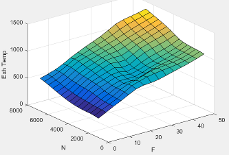
Exhaust Temperature - Simple Torque Lookup
The lookup table for the exhaust temperature is a function of injected fuel mass and engine speed
where:
is exhaust temperature, in K.
F is injected fuel mass, in mg per injection.
N is engine speed, in rpm.
Programmatic Use
To set the block parameter value programmatically, use
the set_param function.
To get the block parameter value
programmatically, use the get_param function.
| Parameter: | f_t_exh |
| Values: | array |
| Data Types: | double |
Dependencies
To enable this parameter, for Torque model, select
Simple Torque Lookup.
Engine load breakpoints used for exhaust temperature lookup table, in mg per injection.
Programmatic Use
To set the block parameter value programmatically, use
the set_param function.
To get the block parameter value
programmatically, use the get_param function.
| Parameter: | f_t_exh_f_bpt |
| Values: | vector |
| Data Types: | double |
Dependencies
To enable this parameter, for Torque model, select
Simple Torque Lookup.
Engine speed breakpoints used for exhaust temperature lookup table, in rpm.
Programmatic Use
To set the block parameter value programmatically, use
the set_param function.
To get the block parameter value
programmatically, use the get_param function.
| Parameter: | f_t_exh_n_bpt |
| Values: | vector |
| Data Types: | double |
Dependencies
To enable this parameter, for Torque model, select
Simple Torque Lookup.
Exhaust Temperature - Torque Structure
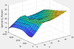
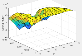
The optimal exhaust manifold gas temperature lookup table, ƒTexh, is a function of the engine speed engine speed and injected fuel mass, Texhopt = ƒTexh(F,N), where:
Texhopt is optimal exhaust manifold gas temperature, in K.
F is compression stroke injected fuel mass, in mg per injection.
N is engine speed, in rpm.
Programmatic Use
To set the block parameter value programmatically, use
the set_param function.
To get the block parameter value
programmatically, use the get_param function.
| Parameter: | f_tqs_exht |
| Values: | array |
| Data Types: | double |
Dependencies
To enable this parameter, for Torque model, select
Torque Structure.
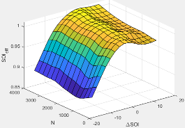
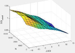
The main start of injection (SOI) timing exhaust temperature efficiency multiplier lookup table, ƒSOIexhteff, is a function of the engine speed engine speed and injected fuel mass, SOIexhteff = ƒSOIexhteff(ΔSOI,N), where:
SOIexhteff is main SOI exhaust temperature efficiency multiplier, dimensionless.
ΔSOI is main SOI timing relative to optimal timing, in degBTDC.
N is engine speed, in rpm.
Programmatic Use
To set the block parameter value programmatically, use
the set_param function.
To get the block parameter value
programmatically, use the get_param function.
| Parameter: | f_tqs_exht_mainsoi_eff |
| Values: | array |
| Data Types: | double |
Dependencies
To enable this parameter, for Torque model, select
Torque Structure.
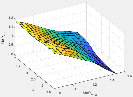
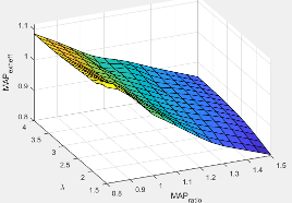
The intake manifold gas pressure exhaust temperature efficiency multiplier lookup table, ƒMAPexheff, is a function of the intake manifold gas pressure ratio relative to optimal pressure ratio and lambda, MAPexheff = ƒMAPexheff(MAPratio,λ), where:
MAPexheff is intake manifold gas pressure exhaust temperature efficiency multiplier, dimensionless.
MAPratio is intake manifold gas pressure ratio relative to optimal pressure ratio, dimensionless.
λ is intake manifold gas lambda, dimensionless.
Programmatic Use
To set the block parameter value programmatically, use
the set_param function.
To get the block parameter value
programmatically, use the get_param function.
| Parameter: | f_tqs_exht_map_eff |
| Values: | array |
| Data Types: | double |
Dependencies
To enable this parameter, for Torque model, select
Torque Structure.
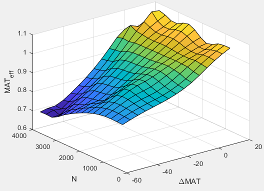
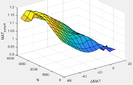
The intake manifold gas temperature exhaust temperature efficiency multiplier lookup table, ƒMATexheff, is a function of the engine speed and intake manifold gas temperature relative to optimal temperature, MATexheff = ƒMATexheff(ΔMAT,N), where:
MATexheff is intake manifold gas temperature exhaust temperature efficiency multiplier, dimensionless.
ΔMAT is intake manifold gas temperature relative to optimal temperature, in K.
N is engine speed, in rpm.
Programmatic Use
To set the block parameter value programmatically, use
the set_param function.
To get the block parameter value
programmatically, use the get_param function.
| Parameter: | f_tqs_exht_mat_eff |
| Values: | array |
| Data Types: | double |
Dependencies
To enable this parameter, for Torque model, select
Torque Structure.
The intake manifold gas oxygen exhaust temperature efficiency multiplier lookup table, ƒO2Pexheff, is a function of the engine speed and intake manifold gas oxygen percent relative to optimal, O2Pexheff = ƒO2Pexheff(ΔO2P,N), where:
O2Pexheff is intake manifold gas oxygen exhaust temperature efficiency multiplier, dimensionless.
ΔO2P is intake gas oxygen percent relative to optimal, in percent.
N is engine speed, in rpm.
Programmatic Use
To set the block parameter value programmatically, use
the set_param function.
To get the block parameter value
programmatically, use the get_param function.
| Parameter: | f_tqs_exht_o2pct_eff |
| Values: | array |
| Data Types: | double |
Dependencies
To enable this parameter, for Torque model, select
Torque Structure.
The fuel rail pressure efficiency exhaust temperature multiplier lookup table, ƒFUELPexheff, is a function of the engine speed and fuel rail pressure relative to optimal breakpoints, FUELPexheff = ƒFUELPexheff(ΔFUELP,N), where:
FUELPexheff is fuel rail pressure exhaust temperature efficiency multiplier, dimensionless.
ΔFUELP is fuel rail pressure relative to optimal, in MPa.
N is engine speed, in rpm.
Programmatic Use
To set the block parameter value programmatically, use
the set_param function.
To get the block parameter value
programmatically, use the get_param function.
| Parameter: | f_tqs_exht_fuelpress_eff |
| Values: | array |
| Data Types: | double |
Dependencies
To enable this parameter, for Torque model, select
Torque Structure.
Post-injection cylinder wall heat loss transfer coefficient, in W/K.
Programmatic Use
To set the block parameter value programmatically, use
the set_param function.
To get the block parameter value
programmatically, use the get_param function.
| Parameter: | f_tqs_exht_post_inj_wall_htc |
| Values: | 0 (default) | scalar |
| Data Types: | double |
Dependencies
To enable this parameter, for Torque model, select
Torque Structure.
Emissions
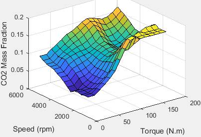
The CI Core Engine CO2 emission mass fraction lookup table is a function of engine torque and engine speed, CO2 Mass Fraction = ƒ(Speed, Torque), where:
CO2 Mass Fraction is the CO2 emission mass fraction, dimensionless.
Speed is engine speed, in rpm.
Torque is engine torque, in N·m.
Programmatic Use
To set the block parameter value programmatically, use
the set_param function.
To get the block parameter value
programmatically, use the get_param function.
| Parameter: | f_CO2_frac |
| Values: | array |
| Data Types: | double |
Dependencies
To enable this parameter, on the Exhaust tab, select CO2.
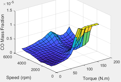
The CI Core Engine CO emission mass fraction lookup table is a function of engine torque and engine speed, CO Mass Fraction = ƒ(Speed, Torque), where:
CO Mass Fraction is the CO emission mass fraction, dimensionless.
Speed is engine speed, in rpm.
Torque is engine torque, in N·m.
Programmatic Use
To set the block parameter value programmatically, use
the set_param function.
To get the block parameter value
programmatically, use the get_param function.
| Parameter: | f_CO_frac |
| Values: | array |
| Data Types: | double |
Dependencies
To enable this parameter, on the Exhaust tab, select CO.
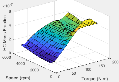
The CI Core Engine HC emission mass fraction lookup table is a function of engine torque and engine speed, HC Mass Fraction = ƒ(Speed, Torque), where:
HC Mass Fraction is the HC emission mass fraction, dimensionless.
Speed is engine speed, in rpm.
Torque is engine torque, in N·m.
Programmatic Use
To set the block parameter value programmatically, use
the set_param function.
To get the block parameter value
programmatically, use the get_param function.
| Parameter: | f_HC_frac |
| Values: | array |
| Data Types: | double |
Dependencies
To enable this parameter, on the Exhaust tab, select HC.
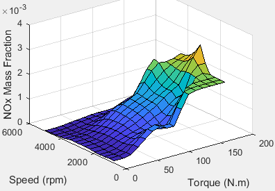
The CI Core Engine NOx emission mass fraction lookup table is a function of engine torque and engine speed, NOx Mass Fraction = ƒ(Speed, Torque), where:
NOx Mass Fraction is the NOx emission mass fraction, dimensionless.
Speed is engine speed, in rpm.
Torque is engine torque, in N·m.
Programmatic Use
To set the block parameter value programmatically, use
the set_param function.
To get the block parameter value
programmatically, use the get_param function.
| Parameter: | f_NOx_frac |
| Values: | array |
| Data Types: | double |
Dependencies
To enable this parameter, on the Exhaust tab, select NOx.
The CI Core Engine PM emission mass fraction lookup table is a function of engine torque and engine speed where:
PM is the PM emission mass fraction, dimensionless.
Speed is engine speed, in rpm.
Torque is engine torque, in N·m.
Programmatic Use
To set the block parameter value programmatically, use
the set_param function.
To get the block parameter value
programmatically, use the get_param function.
| Parameter: | f_PM_frac |
| Values: | array |
| Data Types: | double |
Dependencies
To enable this parameter, on the Exhaust tab, select PM.
Engine speed breakpoints used for the emission mass fractions lookup tables, in rpm.
Programmatic Use
To set the block parameter value programmatically, use
the set_param function.
To get the block parameter value
programmatically, use the get_param function.
| Parameter: | f_exhfrac_n_bpt |
| Values: | vector |
| Data Types: | double |
Dependencies
To enable this parameter, on the Exhaust tab, select CO2, CO, NOx, HC, or PM.
Engine torque breakpoints used for the emission mass fractions lookup tables, in N·m.
Programmatic Use
To set the block parameter value programmatically, use
the set_param function.
To get the block parameter value
programmatically, use the get_param function.
| Parameter: | f_exhfrac_trq_bpt |
| Values: | vector |
| Data Types: | double |
Dependencies
To enable this parameter, on the Exhaust tab, select CO2, CO, NOx, HC, or PM.
Fuel
References
[1] Heywood, John B. Internal Combustion Engine Fundamentals. New York: McGraw-Hill, 1988.
Extended Capabilities
Version History
Introduced in R2017a