Phase Modulation Examples
These examples demonstrate phase modulation (PM) techniques.
Compare Phase Noise Effects on PSK and PAM Signals
Compare PSK and PAM modulation schemes to demonstrate that PSK is more sensitive to phase noise. PSK is more sensitive to phase noise because the PSK constellation is circular, while the PAM constellation is linear.
Specify the number of symbols and the modulation order parameters. Generate random data symbols.
len = 10000;
M = 16;
msg = randi([0 M-1],len,1);
Create a phase noise System object™ and show the configured settings.
phasenoise = comm.PhaseNoise(Level=[-70 -80])
phasenoise =
  comm.PhaseNoise with properties:

              Level: [-70 -80]
    FrequencyOffset: [2000 20000]
         SampleRate: 1000000
       RandomStream: 'Global stream'
Modulate msg using both PSK and PAM to compare the two methods.
txpsk = pskmod(msg,M);
txpam = pammod(msg,M);
Perturb the phase of the modulated signals.
rxpsk = phasenoise(txpsk);
rxpam = phasenoise(txpam);
Create scatter plots of the received signals.
scatterplot(rxpsk);
title('Noisy PSK Scatter Plot')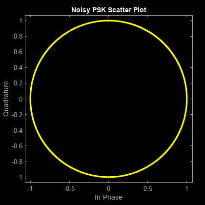
scatterplot(rxpam);
title('Noisy PAM Scatter Plot')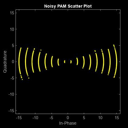
Demodulate the received signals.
recovpsk = pskdemod(rxpsk,M);
recovpam = pamdemod(rxpam,M);
Compute the number of symbol errors for each modulation scheme. The PSK signal experiences a much greater number of symbol errors.
numerrs_psk = symerr(msg,recovpsk);
numerrs_pam = symerr(msg,recovpam);
[numerrs_psk numerrs_pam]
ans = 1×2

   795     3
Compare DQPSK Signal Constellation Points and Transitions
This model plots the output of the DQPSK Modulator Baseband block. The image shows the possible transitions from each symbol in the DQPSK signal constellation to the next symbol.
![]()
The doc_dqpsk_plot uses these blocks:
Complex to Real-Imag (Simulink)
XY Graph (for more information, see Visualize Simulation Data on XY Plot (Simulink))
For the Random Integer Generator block, set the M-ary number to 4, set the initial seed to any positive integer scalar (to randomize results you can use the output of the randn function), and set the sample time to .01.
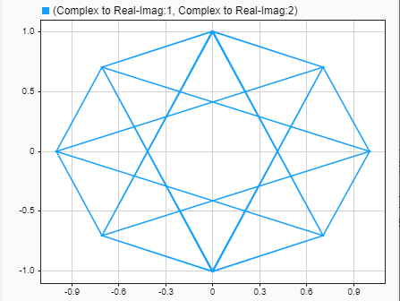
The plot illustrates pi/4-DQPSK modulation because the default phase offset in the DQPSK Modulator Baseband block is pi/4. To see how the phase offset influences the signal constellation, change the Phase offset parameter in the DQPSK Modulator Baseband block to pi/8 or another value. Run the model again and observe how the plot changes.
GPU-Based Convolutionally Encode and Viterbi Decode 8-PSK Modulated Data
Create a GPU-based convolutional encoder System object.
conEnc = comm.gpu.ConvolutionalEncoder;
Create a GPU-based phase shift keying (PSK) modulator System object that accepts a bit input signal.
modPSK = comm.gpu.PSKModulator(BitInput=true);
Create a GPU-based PSK demodulator System object that outputs a column vector of bit values.
demodPSK = comm.gpu.PSKDemodulator(BitOutput=true);
Create a GPU-based Viterbi decoder System object that accepts an input vector of hard decision values, which are zeros or ones.
vDec = comm.gpu.ViterbiDecoder(InputFormat='Hard');Create an error rate System object that ignores 3 data samples before making comparisons. The received data lags behind the transmitted data by 34 samples.
error = comm.ErrorRate(ComputationDelay=3,ReceiveDelay=34);
Run the simulation by using this for-loop to process data. Add white noise for 7 dB SNR to a 0 dBW signal.
for counter = 1:20
    data = randi([0 1],30,1);
    encodedData = conEnc(gpuArray(data));
    modSignal = modPSK(encodedData);
    receivedSignal = awgn(modSignal,7);
    demodSignal = demodPSK(receivedSignal);
    receivedBits = vDec(demodSignal);
    errors = error(data,gather(receivedBits));
end
Display the number of errors.
errors(2)
ans =
5
See Also
Functions
rcosdesign|dpskmod|dpskdemod|pskmod|pskdemod
Objects
comm.RaisedCosineTransmitFilter|comm.RaisedCosineReceiveFilter|comm.DBPSKModulator|comm.DBPSKDemodulator|comm.DPSKModulator|comm.DPSKDemodulator|comm.DQPSKModulator|comm.DQPSKDemodulator|comm.OQPSKModulator|comm.OQPSKDemodulator|comm.gpu.PSKModulator|comm.gpu.PSKDemodulator
Blocks
- Raised Cosine Transmit Filter | Raised Cosine Receive Filter | Bipolar to Unipolar Converter | Unipolar to Bipolar Converter | Data Mapper | BPSK Modulator Baseband | BPSK Demodulator Baseband | DBPSK Modulator Baseband | DBPSK Demodulator Baseband | DQPSK Modulator Baseband | DQPSK Demodulator Baseband | M-DPSK Modulator Baseband | M-DPSK Demodulator Baseband | M-PSK Modulator Baseband | M-PSK Demodulator Baseband | OQPSK Modulator Baseband | OQPSK Demodulator Baseband | QPSK Modulator Baseband | QPSK Demodulator Baseband