Plug Custom Channel into Wireless Network Simulator
This example shows you how to plug a custom channel into a wireless network simulator and compare its performance against a free-space propagation loss (FSPL) channel. Using this example, you can:
Configure a 5G network with new radio (NR) base station (gNB) and user equipment (UE) nodes.
Establish a connection between the gNB and UE nodes.
Create a custom channel, and plug it into a wireless network simulator.
Simulate a 5G network, and retrieve the statistics of the gNB and UE nodes.
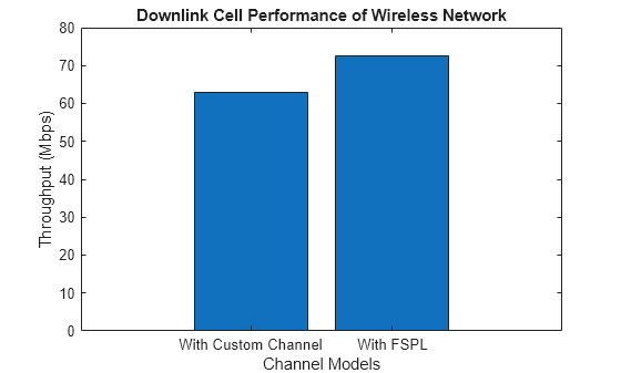
Compare the throughput performance for custom and FSPL channels.
Configure Wireless Network Simulator
Create a wireless network simulator.
rng("default")
networkSimulator = wirelessNetworkSimulator.init;
Create a gNB node with these specifications.
Position – [-100 100 0]
Channel bandwidth – 20 MHz
Subcarrier spacing – 30 kHz
Duplex mode – Frequency division duplex
gnb = nrGNB(Position=[-100 100 0],ChannelBandwidth=20e6,DuplexMode="FDD",SubcarrierSpacing=30e3);Create two UE nodes, specifying their positions in Cartesian coordinates.
ue = nrUE(Position=[100 100 0; 5000 100 0]);
Connect the UE nodes to the gNB node, enabling full-buffer traffic in the downlink direction.
connectUE(gnb,ue,FullBufferTraffic="DL")Add the nodes to the wireless network simulator.
addNodes(networkSimulator,gnb)
addNodes(networkSimulator,ue)
Set Up 5G CDL Channel Model
Create an individual downlink clustered delay line (CDL) channel for each UE node.
% Retrieve OFDM information based on the number of resource blocks and
% subcarrier spacing (kHz)
waveformInfo = nrOFDMInfo(gnb.NumResourceBlocks,gnb.SubcarrierSpacing/1e3);
channelFilteringFlag = strcmp(gnb.PHYAbstractionMethod,"none");

% Calculate the total number of nodes by adding up the number of gNBs and UEs
numNodes = max([gnb.ID, ue.ID]);

% Initialize the CDL channel cell array, maximum channel delay matrix, and the path filter cell array
channelInfo.CDLChannels = cell(numNodes,numNodes);
channelInfo.MaxChannelDelayMatrix = zeros(numNodes,numNodes);
channelInfo.PathFilter = cell(numNodes,numNodes);

% Create a CDL channel for each gNB-UE link
for i = 1:length(ue)
    % Create a CDL channel model by specifying sample rate and channel filtering option
    channelInfo.CDLChannels{gnb.ID,ue(i).ID} = nrCDLChannel(SampleRate=waveformInfo.SampleRate,ChannelFiltering=channelFilteringFlag);
    % Set the transmit antenna array size
    channelInfo.CDLChannels{gnb.ID,ue(i).ID}.TransmitAntennaArray.Size = [1 1 1 1 1];
    %  Set the receive antenna array size
    channelInfo.CDLChannels{gnb.ID,ue(i).ID}.ReceiveAntennaArray.Size = [1 1 1 1 1];
    % Retrieve the channel information
    chInfo = info(channelInfo.CDLChannels{gnb.ID,ue(i).ID});
    % Calculate the maximum channel delay and update the delay matrix
    channelInfo.MaxChannelDelayMatrix(gnb.ID,ue(i).ID) = ceil(max(chInfo.PathDelays*waveformInfo.SampleRate)) + chInfo.ChannelFilterDelay;
    % Obtain path filters
    channelInfo.PathFilter{gnb.ID,ue(i).ID} = getPathFilters(channelInfo.CDLChannels{gnb.ID,ue(i).ID}).';
end
Compute Custom Channel Statistics
Add the custom channel to the wireless network simulator.
addChannelModel(networkSimulator,@(rxInfo,txData)addImpairment(channelInfo,rxInfo,txData))
Specify the simulation time in seconds.
simulationTime = 0.05;
Run the simulation for the specified simulation time.
run(networkSimulator,simulationTime)
Obtain the statistics for the gNB and UE nodes.
gnbStatsCustomChannel = statistics(gnb);
ueStatsCustomChannel = statistics(ue);
% Display MAC layer statistics for the UEs
ueStatsCustomChannel.MAC
ans = struct with fields:
TransmittedPackets: 0
TransmittedBytes: 0
ReceivedPackets: 99
ReceivedBytes: 313753
Retransmissions: 0
RetransmissionBytes: 0
DLTransmissionRB: 2550
DLRetransmissionRB: 0
ULTransmissionRB: 0
ULRetransmissionRB: 0
ans = struct with fields:
     TransmittedPackets: 0
       TransmittedBytes: 0
        ReceivedPackets: 99
          ReceivedBytes: 80180
        Retransmissions: 0
    RetransmissionBytes: 0
       DLTransmissionRB: 2550
     DLRetransmissionRB: 0
       ULTransmissionRB: 0
     ULRetransmissionRB: 0
Calculate the total downlink throughput (Mbps) across both UEs.
dlReceivedBytesTotal = ueStatsCustomChannel(1).MAC.ReceivedBytes + ueStatsCustomChannel(2).MAC.ReceivedBytes;
dlThroughputWithCustomChannel = (dlReceivedBytesTotal*8) / (simulationTime*1000*1000);
Set Up FSPL Channel for Analysis
Run the same scenario with FSPL channel only. Initialize, configure nodes, connect, run, and compute throughput.
rng("default")
networkSimulator = wirelessNetworkSimulator.init;
% Recreate the gNB and UEs nodes
gnb = nrGNB(Position=[-100 100 0],ChannelBandwidth=20e6, ...
                   DuplexMode="FDD",SubcarrierSpacing=30e3);
ue = nrUE(Position=[100 100 0; 5000 100 0]);                  % In Cartesian x, y, and z coordinates

% Connect and add nodes
connectUE(gnb,ue,FullBufferTraffic="DL")
addNodes(networkSimulator,gnb)
addNodes(networkSimulator,ue)
%  Run FSPL-only simulation
run(networkSimulator,simulationTime)
Obtain the statistics for the gNB and UE nodes.
gnbStats = statistics(gnb);
ueStats = statistics(ue);
% Display MAC layer statistics for the UEs
ueStats.MAC
ans = struct with fields:
TransmittedPackets: 0
TransmittedBytes: 0
ReceivedPackets: 99
ReceivedBytes: 313753
Retransmissions: 0
RetransmissionBytes: 0
DLTransmissionRB: 2550
DLRetransmissionRB: 0
ULTransmissionRB: 0
ULRetransmissionRB: 0
ans = struct with fields:
     TransmittedPackets: 0
       TransmittedBytes: 0
        ReceivedPackets: 99
          ReceivedBytes: 140180
        Retransmissions: 0
    RetransmissionBytes: 0
       DLTransmissionRB: 2550
     DLRetransmissionRB: 0
       ULTransmissionRB: 0
     ULRetransmissionRB: 0
Calculate the total downlink throughput (Mbps) across both UEs.
dlReceivedBytesTotal = ueStats(1).MAC.ReceivedBytes + ueStats(2).MAC.ReceivedBytes;
dlThroughputWithFSPL = (dlReceivedBytesTotal*8)/(simulationTime*1000*1000);
Visualize Throughput
Compare throughput for custom and FSPL channels using a bar chart.
networkSimulator = wirelessNetworkSimulator.init;
% Create a bar chart with two bars: one for the custom channel, one for the FSPL.
data = [dlThroughputWithCustomChannel dlThroughputWithFSPL]; % The heights of the two bars
labels = {"With Custom Channel","With FSPL"};                 % Labels for the bars

% Plot the bar chart
bar(data)

% Customize the x-axis labels
set(gca,"XTickLabel",labels)

% Add title and labels
title("Downlink Cell Performance of Wireless Network")
xlabel("Channel Models")
ylabel("Throughput (Mbps)")
Local Function
Follow these steps to create a custom channel model.
Create a custom function with this syntax:
rxData = customFcnName(rxInfo,txData). TherxInfoinput is a structure containing the receiver node information, and thetxDatainput is a structure that specifies the transmitted packets. The simulator automatically passes information about the receiver node and the packets transmitted by a transmitter node as inputs to the custom function. For more information, see theaddChannelModelobject function.When you add a custom channel to the 5G SLS, update the
Power,Duration, andDatafields (for full PHY) in the wireless packet metadata. Also, update thePathGain,PathFilters,PathDelaysandSampleTimefields inMetadata.Channel. You do not need to includePathDelaysfor 5G. For more information about the packet structure, refer towirelessPacket.Apply free space path loss between the base station and UE nodes.
Apply a CDL channel to the transmitted packets.
function outputData = addImpairment(channelInfo,rxInfo,txData)

outputData = txData;

% Calculate path loss
distance = norm(txData.TransmitterPosition - rxInfo.Position); % Distance between transmitter and receiver
lambda = physconst("LightSpeed")/txData.CenterFrequency;       % Calculate wavelength
pathLoss = fspl(distance,lambda);                              % FSPL
outputData.Power = outputData.Power - pathLoss;                % Adjust power of output data based on path loss

% Obtain the maximum channel delay matrix from the channel model information
maxChannelDelayMatrix = channelInfo.MaxChannelDelayMatrix;

% Obtain the path filter from the channel model information
pathFilter = channelInfo.PathFilter;

% Check if the CDL channel model exists for the given transmitter-receiver pair
if ~isempty(channelInfo.CDLChannels{txData.TransmitterID,rxInfo.ID})

    % A channel exists between the transmitter and receiver nodes
    channelInfo.CDLChannels{txData.TransmitterID,rxInfo.ID}.InitialTime = outputData.StartTime;
    if outputData.Abstraction == 0                                                                          % Full PHY
        rxWaveform = [txData.Data; zeros(maxChannelDelayMatrix(txData.TransmitterID,rxInfo.ID), ...
            size(txData.Data,2))];
        [outputData.Data,outputData.Metadata.Channel.PathGains,outputData.Metadata.Channel.SampleTimes] = ...
            channelInfo.CDLChannels{txData.TransmitterID,rxInfo.ID}(rxWaveform);
        outputData.Data = outputData.Data.*db2mag(-pathLoss);
        outputData.Duration = outputData.Duration + ...
            (1/outputData.SampleRate)*maxChannelDelayMatrix(txData.TransmitterID,rxInfo.ID);
    else                                                                                                    % Abstract PHY
        channelInfo.CDLChannels{txData.TransmitterID,rxInfo.ID}.NumTimeSamples =  ...
            txData.Metadata.NumSamples + maxChannelDelayMatrix(txData.TransmitterID,rxInfo.ID);
        [outputData.Metadata.Channel.PathGains,outputData.Metadata.Channel.SampleTimes] = ...
            channelInfo.CDLChannels{txData.TransmitterID,rxInfo.ID}();
    end
    outputData.Metadata.Channel.PathFilters = ...
        pathFilter{txData.TransmitterID,rxInfo.ID};
else
    % Set default values for channel parameters
    outputData.Metadata.Channel.PathGains = ...
        permute(ones(outputData.NumTransmitAntennas, ...
        rxInfo.NumReceiveAntennas), ...
        [3 4 1 2]) / sqrt(rxInfo.NumReceiveAntennas);
    outputData.Metadata.Channel.PathFilters = 1;
    outputData.Metadata.Channel.SampleTimes = 0;

    if outputData.Abstraction == 0                            % Full PHY
        outputData.Data = outputData.Data.*db2mag(-pathLoss);
        numTxAnts = outputData.NumTransmitAntennas;
        numRxAnts = rxInfo.NumReceiveAntennas;
        H = fft(eye(max([numTxAnts numRxAnts])));
        H = H(1:numTxAnts,1:numRxAnts);
        H = H/norm(H);
        outputData.Data = txData.Data*H;                      % Apply channel to the waveform
    end
end
end