Contenu principal

Scene

R2026b

Multi-mesh scene with hierarchical transform graph

Since R2026b

Description

Add-On Required: This feature requires the 3D Asset Processing Library for MATLAB add-on.

The asset3d.Scene object represents a collection of meshes organized in a hierarchical transform graph.

Use this object to group multiple Mesh objects into a single scene with parent-child relationships and per-node transformations. You can visualize the scene in an interactive 3D viewer, inspect the hierarchy, extract sub-scenes, flatten the scene to individual meshes, and apply spatial transformations that propagate through the graph.

Creation

Description

sceneObj = asset3d.Scene creates an empty scene object sceneObj with no geometry.

example

sceneObj = asset3d.Scene(geometries) creates a scene object sceneObj containing the specified meshes geometries.

Input Arguments

expand all

Meshes to include in the scene, specified as one of these values:

  • Array of Mesh objects — Meshes are auto-named as "geometry_0", "geometry_1", and so on.

  • Cell array of Mesh objects — Meshes are auto-named as "geometry_0", "geometry_1", and so on.

  • Dictionary mapping string names to Mesh objects — The dictionary keys become the geometry names.

Output Arguments

expand all

Multi-mesh scene object, returned as a Scene object.

Properties

expand all

This property is read-only.

Named geometries in the scene, represented as a dictionary mapping string names to Mesh objects.

This property is read-only.

Scene graph information, represented as a structure with these fields:

  • BaseFrame — Name of the root node, represented as a string. The default base frame name is "world".

  • Nodes — All node names in the scene graph, represented as an N-by-1 string array. N is the total number of nodes. This includes every node in the hierarchy including geometry-bearing nodes and if available, intermediate transform-only nodes. The base frame node is not included in this array.

  • Edges — Parent-child edges, represented as an E-by-2 cell array. E is the number of edges. Each row is a {parentNode, childNode} pair.

  • Geometries — Geometry-bearing nodes, represented as an M-by-1 structure array. M is the number of nodes that have attached geometry. Note that, the array contains nodes with a non-empty geometry name and does not include the intermediate transform-only nodes. Each element has these fields:

    • Node — Name of the scene-graph node that carries this geometry, represented as a string.

    • GeometryName — Key into the Geometry dictionary, represented as a string. Use this key to retrieve the corresponding Mesh object.

    • Transform — Absolute 4-by-4 homogeneous transformation matrix for this node, represented as a matrix.

Use the addMesh, removeMesh, and subscene functions to build and modify the hierarchy.

This property is read-only.

Axis-aligned bounding box of the entire scene, represented as a 2-by-3 matrix of the form [min; max] where the three columns correspond to the x-, y-, and z-axes.

Data Types: double

This property is read-only.

Geometric center of the scene, represented as a three-element row vector of the form [x y z].

Data Types: double

This property is read-only.

Bounding box dimensions, represented as a three-element row vector of the form [dx dy dz].

Data Types: double

This property is read-only.

Total surface area of all geometries in the scene, represented as a scalar.

Data Types: double

This property is read-only.

Total volume of all geometries in the scene, represented as a scalar.

Data Types: double

This property is read-only.

Up axis convention, represented as "X", "Y", or "Z". Use the setUpAxis function to change the up axis convention.

Data Types: string

Object Functions

showDisplay mesh or scene object in interactive 3D viewer
dispGraphDisplay scene hierarchy as text tree
addMeshAdd mesh to scene
removeMeshRemove mesh from scene
flattenFlatten scene into meshes with transforms
subsceneExtract sub-scene from specified node
patchConvert mesh or scene object to patch for visualization in axes
snapshotCapture snapshot of mesh or scene as image
transformApply homogeneous transformation to mesh or scene object
rotateRotate mesh or scene object
translateTranslate mesh or scene object using translation vector
scaleScale mesh or scene object
resizeResize mesh or scene object to absolute dimensions in world units
setUpAxisChange up axis convention for mesh or scene object
copyCreate copy of mesh or scene object

Examples

collapse all

Create two meshes, a big rectangle mesh and another small rectangle mesh.

faces = [1 2 3; 1 3 4; 5 7 6; 5 8 7; 1 5 6; 1 6 2; 2 6 7; 2 7 3; 3 7 8; 3 8 4; 4 8 5; 4 5 1];

bigVerts = [0 0 0; 4 0 0; 4 3 0; 0 3 0; 0 0 1; 4 0 1; 4 3 1; 0 3 1];
bigMesh = asset3d.Mesh(bigVerts,faces,FaceColors=uint8([70 130 180]));

smallVerts = [0 0 0; 2 0 0; 2 1.5 0; 0 1.5 0; 0 0 0.8; 2 0 0.8; 2 1.5 0.8; 0 1.5 0.8];
smallMesh = asset3d.Mesh(smallVerts,faces,FaceColors=uint8([200 80 80]));

Create an empty scene with a base frame name.

scene = asset3d.Scene(BaseFrame="scene_model");

Add meshes to the scene with a big rectangle on the bottom and a small rectangle on top.

T = eye(4);
T(1:3,4) = [1; 0.75; 1];

addMesh(scene,bigMesh,Name="big_rect",NodeName="base")
addMesh(scene,smallMesh,Name="small_rect",NodeName="top",ParentNodeName="base",Transform=T)

Display the scene hierarchy. The |dispGraph| function shows the base frame name and the parent-child relationships between nodes.

dispGraph(scene)
scene_model
    └── base [Mesh: 12 faces]
        └── top [Mesh: 12 faces]

Display the scene.

show(scene,Grid=true)
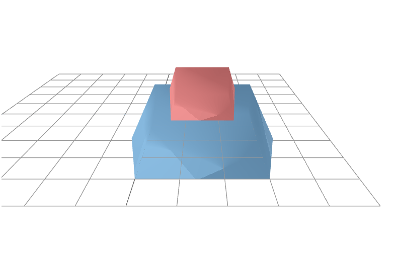
Displays a scene with a big rectangle on the bottom and a small rectangle on top.

Version History

Introduced in R2026b