idealGroundTruthSensor
Generate ground truth measurements as sensor detections or track reports from driving scenario or RoadRunner Scenario
Since R2025a
Description
The idealGroundTruthSensor
System object™ generates detections or track reports for ground-truth measurements of all the
targets in the field-of-view of the sensor. The sensor also generates ground-truth
measurements for lane boundaries in the scenario. You can mount the
idealGroundTruthSensor on a vehicle and use it in a scenario containing other actors
and trajectories created using a drivingScenario object.
You can also use the idealGroundTruthSensor object with vehicle actors in RoadRunner Scenario simulation. First you must create a SensorSimulation object to interface sensors with RoadRunner Scenario, and then register the sensor model using the addSensors object function before simulation.
To generate ideal ground-truth detections:
Create the
idealGroundTruthSensorobject and set its properties.Call the object with arguments, as if it were a function.
To learn more about how System objects work, see What Are System Objects?
Creation
Description
idealGTSensor = idealGroundTruthSensor
idealGTSensor = idealGroundTruthSensor(Name=Value)idealGroundTruthSensor(DetectionCoordinates="Host
Coordinates",MaxRange=200) creates an ideal ground truth sensor that reports
detections in the host vehicle coordinate system and has a maximum detection range of 200
meters.
Properties
Usage
Syntax
Description
Generate Detections
This syntax applies when you set the TargetReportFormat property to 'Object Detections' and
the DetectorOutput property to 'Objects Only'.
[
returns ground truth object detections dets,numReports,isValidTime] = idealGTSensor()dets for actors in field of
view, number of valid detections reported, numReports, and a
logical value isValidTime indicating whether
simTime is a valid time for generating detections. If
simTime is an integer multiple of the UpdateInterval property value, then isValidTime is
1 (true).
Generate Tracks
This syntax applies when you set the TargetReportFormat property to 'Tracks and the DetectorOutput property to 'Objects Only'..
[
returns ground truth object tracks tracks,numReports,isValidTime] = idealGTSensor()tracks for actors in field of
view, number of valid tracks reported, numReports, and a logical
value isValidTime indicating whether simTime
is a valid time for generating detections. If simTime is an integer
multiple of the UpdateInterval property value, then isValidTime is
1 (true).
Generate Target Poses
This syntax applies when you set the TargetReportFormat property to 'Target Poses' and the
DetectorOutput property to 'Objects Only'.
[
returns ground truth target poses poses,numReports,isValidTime] = idealGTSensor()poses for actors in field of
view, number of valid poses reported, numReports, and a logical
value isValidTime indicating whether simTime
is a valid time for generating detections. If simTime is an integer
multiple of the UpdateInterval property value, then isValidTime is
1 (true).
Generate Lane Detections Along with Object Detections, Tracks or Target Poses
This syntax applies when you set the DetectorOutput property to 'Objects and Lanes'.
[___,
also returns ground truth lane detections numReports,isValidTime,laneDets,numValidLaneDets,isValidLaneTime] = idealGTSensor()laneDets along with
object detections, tracks or target poses using any of the previous syntaxes. This
syntax also returns the number of valid lane detections reported,
numValidLaneDets, and a flag,
isValidLaneTime, indicating whether the required simulation time
to generate lane detections has elapsed.
Output Arguments
Generated detections, returned as a cell array of objectDetection objects. Each object contains these properties:
| Property | Definition |
|---|---|
Time | Measurement time |
Measurement | Object measurements |
MeasurementNoise | Measurement noise covariance matrix |
SensorIndex | Unique ID of the sensor |
ObjectClassID | Object classification |
MeasurementParameters | Parameters used by initialization functions of nonlinear Kalman tracking filters |
ObjectAttributes | Additional information passed to tracker |
For rectangular coordinates, Measurement and
MeasurementNoise are reported in the rectangular coordinate
system specified by the DetectionCoordinates property of the
idealGroundTruthSensor object.
For spherical coordinates, Measurement and
MeasurementNoise are reported in the spherical coordinate
system, which is based on the sensor rectangular coordinate system.
Measurement and
MeasurementNoise
DetectionCoordinates Value | Measurement and
MeasurementNoise Coordinates | |||||||||||||||
|---|---|---|---|---|---|---|---|---|---|---|---|---|---|---|---|---|
'Body' |
Coordinate Dependence on
| |||||||||||||||
'Sensor rectangular' | ||||||||||||||||
'Sensor spherical' |
Coordinate Dependence on
|
For ObjectAttributes, this table describes the additional
information used for tracking.
ObjectAttributes
| Attribute | Definition |
|---|---|
TargetIndex | Identifier of the actor, ActorID, that generated the
detection. For false alarms, this value is negative. |
SNR | Detection signal-to-noise ratio, in dB. |
For MeasurementParameters, the measurements are relative to
the parent frame. When you set the DetectionCoordinates property
to 'Body', the parent frame is the ego vehicle body. When you set
DetectionCoordinates to 'Sensor rectangular'
or 'Sensor spherical', the parent frame is the sensor.
MeasurementParameters
| Parameter | Definition |
|---|---|
Frame | Enumerated type indicating the frame used to report measurements. When
Frame is set to 'rectangular',
detections are reported in rectangular coordinates. When
Frame is set to 'spherical',
detections are reported in spherical coordinates. |
OriginPosition | 3-D vector offset of the sensor origin from the parent frame origin. |
OriginVelocity | Velocity of the sensor coordinate system with respect to the parent frame. |
Orientation | Orientation of the radar sensor coordinate system with respect to the parent frame. |
IsParentToChild | Logical scalar indicating if Orientation performs a
frame rotation from the parent coordinate frame to the child coordinate
frame. When IsParentToChild is false, then
Orientation performs a frame rotation from the child
coordinate frame to the parent coordinate frame. |
HasAzimuth | Indicates whether measurements contain azimuth components. |
HasElevation | Indicates whether measurements contain elevation components. |
HasRange | Indicates whether measurements contain range components. |
HasVelocity | Indicates whether measurements contain velocity or range rate components. |
Generated tracks, returned as an objectTrack array in
MATLAB® and a structure array in generated code. In generated code, the field
names of the returned structure are same as the property names of the
objectTrack object.
Target poses, in ego vehicle coordinates, returned as a structure or as an array of structures. The pose of the ego vehicle actor is not included.
A target pose defines the position, velocity, and orientation of a target in ego vehicle coordinates. Target poses also include the rates of change in actor position and orientation.
Each pose structure has these fields.
| Field | Description |
|---|---|
ActorID | Scenario-defined actor identifier, specified as a positive integer. |
ClassID | Classification identifier, specified as a nonnegative integer. 0
represents an object of an unknown or unassigned class. |
Position | Position of actor, specified as a real-valued vector of the form [x y z]. Units are in meters. |
Velocity | Velocity (v) of actor in the x-, y-, and z-directions, specified as a real-valued vector of the form [vx vy vz]. Units are in meters per second. |
Roll | Roll angle of actor, specified as a real scalar. Units are in degrees. |
Pitch | Pitch angle of actor, specified as a real scalar. Units are in degrees. |
Yaw | Yaw angle of actor, specified as a real scalar. Units are in degrees. |
AngularVelocity | Angular velocity (ω) of actor in the x-, y-, and z-directions, specified as a real-valued vector of the form [ωx ωy ωz]. Units are in degrees per second. |
For full definitions of these structure fields, see the actor and vehicle functions.
Number of reported detections or tracks, returned as a nonnegative integer.
numReports is equal to the length of dets
when generating detections and tracks when generating
tracks.
Data Types: double
Valid time for generating reports, returned as a logical 0
(false) or 1 (true).
If isValidTime is 0
(false), then the reports returned by dets
(for generated detections) or tracks (for generated tracks) are
invalid because the sensor generated them at a time that is inconsistent with the
sensor update rate.
The sensor generates reports only when the current simulation time is an integer
multiple of the time interval at which the sensor generates reports. This time
interval is equal to the UpdateInterval property value.
Data Types: logical
Lane boundary detections, returned as an array structures. The fields of the structure are:
| Field | Description |
| Lane boundary coordinates, returned as a real-valued N-by-3 matrix, where N is the number of lane boundary coordinates. Lane boundary coordinates define the position of points on the boundary at returned longitudinal distances away from the ego vehicle, along the center of the road. This matrix also includes the boundary coordinates at zero distance from the ego vehicle. These coordinates are to the left and right of the ego vehicle origin, which is located under the center of the rear axle. Units are in meters. |
| Lane boundary curvature at each row of the
Coordinates matrix, returned as a real-valued
N-by-1 vector. N is the number of
lane boundary coordinates. Units are in radians per meter. |
| Derivative of lane boundary curvature at each row of the
Coordinates matrix, returned as a real-valued
N-by-1 vector. N is the number of
lane boundary coordinates. Units are in radians per square meter. |
| Initial lane boundary heading angle, returned as a real scalar. The heading angle of the lane boundary is relative to the ego vehicle heading. Units are in degrees. |
| Lateral offset of the ego vehicle position from the lane boundary, returned as a real scalar. An offset to a lane boundary to the left of the ego vehicle is positive. An offset to the right of the ego vehicle is negative. Units are in meters. In this image, the ego vehicle is offset 1.5 meters from the left lane and 2.1 meters from the right lane.
|
| Type of lane boundary marking, returned as one of these values:
|
| Saturation strength of the lane boundary marking, returned as a
real scalar from 0 to 1. A value of |
| Lane boundary width, returned as a positive real scalar. In a double-line lane marker, the same width is used for both lines and for the space between lines. Units are in meters. |
| Length of dash in dashed lines, returned as a positive real scalar. In a double-line lane marker, the same length is used for both lines. |
| Length of space between dashes in dashed lines, returned as a positive real scalar. In a dashed double-line lane marker, the same space is used for both lines. |

Number of lane detections returned, defined as a nonnegative integer. Maximum
number of lane detections returned is based on the value specified in
MaxNumLanesReported property.
Data Types: double
Valid lane detection time, returned as 0 or
1. isValidLaneTime is 0
when lane detection updates are requested at times that are between update intervals
specified by LaneUpdateInterval.
Data Types: logical
Object Functions
To use an object function, specify the
System object as the first input argument. For
example, to release system resources of a System object named obj, use
this syntax:
release(obj)
Examples
Use an ideal ground truth sensor to generate detections and tracks for all driving scenario actors in the specified field of view. You can also use the ideal ground truth sensor to generate ground truth lane detections in the driving scenario.
Create Driving Scenario and Add Ideal Ground Truth Sensor
Create a driving scenario containing a three-lane road and three vehicles.
[scenario,egoVehicle] = helperCreateDrivingScenario;
targetProfiles = actorProfiles(scenario);
Create an ideal ground truth sensor mounted at the front of the ego vehicle and configure it with these options:
Output ground truth tracks of objects in its field of view.
Output ground truth lane boundaries in field of view.
frontIdealGTSensor = idealGroundTruthSensor(SensorIndex=1,DetectorOutput="Objects and Lanes",SensorLocation=[3.4 0 0.2],...
    PointOnTargetReported="Origin Point",LaneBoundariesReported="All Lanes",TargetOutputFormat="Tracks");
Add a radar sensor at the same location and configure it to show tracks of objects in its field of view.
frontRadar = drivingRadarDataGenerator(SensorIndex=2,UpdateRate=1/scenario.SampleTime,MountingLocation=[3.4 0 0.2], ...
                                   TargetReportFormat="Tracks",Profiles=targetProfiles);
Add a vision sensor at the front roof center of the ego vehicle.
frontVisionSensor = visionDetectionGenerator(SensorIndex=4,UpdateInterval=scenario.SampleTime,SensorLocation=[3.4 0],Height=1.1,Yaw=0, ...
    DetectorOutput="Lanes and objects",ActorProfiles=targetProfiles,MinObjectImageSize=[2 2]);
Create a second ideal ground truth sensor mounted on the left side of the ego vehicle. Add an ultrasonic sensor at the same location.
leftIdealGTSensor = idealGroundTruthSensor(SensorIndex=3,DetectorOutput="Objects Only",SensorLocation=[0.5 1 0.2],Yaw=90, ...
    PointOnTargetReported="Closest Point");

leftUltrasonicSensor = ultrasonicDetectionGenerator(SensorIndex=5,MountingLocation=[0.5 1 0.2],MountingAngles=[90 0 0], ...
    FieldOfView=[70 35],Profiles=targetProfiles);
Add all the sensors to the driving scenario.
sensorSuite = {frontIdealGTSensor,frontRadar,leftIdealGTSensor,frontVisionSensor,leftUltrasonicSensor};
addSensors(scenario,sensorSuite,egoVehicle.ActorID)
Create Bird's-Eye-Plot
bep = helperCreateBEP(sensorSuite);
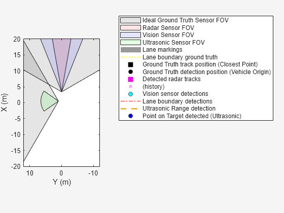
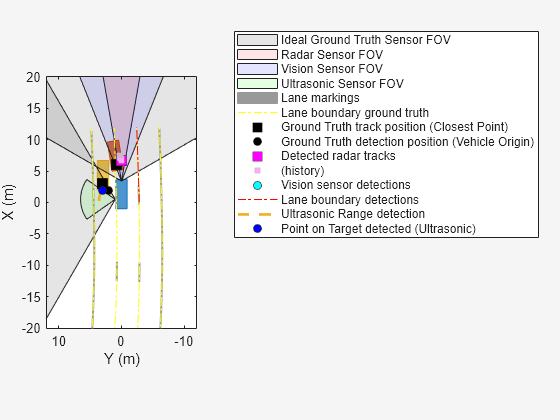
Run the Simulation. Visualize the ideal gound truth measurements and actual sensor measurement using the created bird's-eye-plot.
while advance(scenario)

    % Get target poses
    targets = targetPoses(egoVehicle);

    % Ideal ground truth object and lane boundary detections
    [fIdGTTracks,~,fisValidTime,laneDets,numValidLaneDets,isValidLaneTime] = frontIdealGTSensor();
    [lIdGTDets,~,lisValidTime] = leftIdealGTSensor();

    % Radar tracks
    [radarTracks,~,risValidTime] = frontRadar(targets,scenario.SimulationTime);

    % Vision object and lane boundary detections
    [visionDets,~,visValidTime,visionLaneDets,~,isValidVisionLaneTime] = frontVisionSensor(targets,laneDets,scenario.SimulationTime);
    [ulDets,ulisValidTime] = leftUltrasonicSensor(targets,scenario.SimulationTime);

    % Plot vehicle outlines and lane markings
    [objposition,objyaw,objlength,objwidth,objoriginOffset,color] = targetOutlines(egoVehicle);
    plotOutline(bep.Plotters(6),objposition,objyaw,objlength,objwidth, ...
        OriginOffset=objoriginOffset,Color=color)

    [lmv,lmf] = laneMarkingVertices(egoVehicle);
    plotLaneMarking(bep.Plotters(7),lmv,lmf)

    % Plot ground truth lane boundaries
    if ~isempty(laneDets) && isValidLaneTime
        plotLaneBoundary(bep.Plotters(8),{laneDets.Coordinates})
    end

    % Plot ideal ground truth measurements
    if ~isempty(fIdGTTracks) && fisValidTime
        fIdGTDetPos = cell2mat(cellfun(@(t)t.State(1:2:end),fIdGTTracks,UniformOutput=false)')';
        plotTrack(bep.Plotters(9),fIdGTDetPos)
    end

     if ~isempty(lIdGTDets) && lisValidTime
        lIdGTDetPos = cell2mat(cellfun(@(d)d.Measurement(1:2),lIdGTDets,UniformOutput=false)')';
        plotDetection(bep.Plotters(10),lIdGTDetPos)
    end

    % Plot radar tracks
    if ~isempty(radarTracks) && risValidTime
        trackPos = cell2mat(arrayfun(@(t)t.State(1:2:end),radarTracks,UniformOutput=false)')';
        plotTrack(bep.Plotters(11),trackPos(:,1:2))
    end

    % Plot vision object detections and lane boundaries
    if visValidTime
        visionDetPos = cellfun(@(d)d.Measurement(1:2),visionDets,UniformOutput=false);
        visionDetPos = vertcat(zeros(0,2),cell2mat(visionDetPos')');
        plotDetection(bep.Plotters(12),visionDetPos)
    end

    if isValidVisionLaneTime
        plotLaneBoundary(bep.Plotters(13),vertcat(visionLaneDets.LaneBoundaries))
    end

    % Plot ultrasonic range and point-on-target detections
    if ~isempty(ulDets) && ulisValidTime
        lranges = ulDets{1}.Measurement;
        plotRangeDetection(bep.Plotters(14),lranges,leftUltrasonicSensor.FieldOfView(1),leftUltrasonicSensor.MountingLocation,leftUltrasonicSensor.MountingAngles)
        plotDetection(bep.Plotters(15),ulDets{1}.ObjectAttributes{1}.PointOnTarget(1:2)')
    end
end
Supporting functions
helperCreateDrivingScenario function creates the driving scenario, adds roads and vehicles, and assigns trajectories to all the vehicles.
function [scenario,egovehicle] = helperCreateDrivingScenario
    scenario = drivingScenario;
    roadCenters = [-120 30 0;-60 0 0;0 0 0; 60 0 0; 120 30 0];
    lspc = lanespec(3);
    road(scenario,roadCenters,Lanes=lspc);
    %Create an ego vehicle that travels in the center lane at a velocity of 30 m/s.
    egovehicle = vehicle(scenario,ClassID=1);
    egopath = [1.5 0 0; 60 0 0; 111 25 0];
    egospeed = 30;
    smoothTrajectory(egovehicle,egopath,egospeed);
    % Add a target vehicle that travels ahead of the ego vehicle at 30.5 m/s in the right lane, and changes lanes close to the ego vehicle.
    ftargetcar = vehicle(scenario,ClassID=1);
    ftargetpath = [8 2; 60 -3.2; 120 33];
    ftargetspeed = 30.5;
    smoothTrajectory(ftargetcar,ftargetpath,ftargetspeed);
    % Add a second target vehicle that travels in the left lane at 32m/s.
    ltargetcar = vehicle(scenario,ClassID=1);
    ltargetpath = [-5.0 3.5 0; 60 3.5 0; 111 28.5 0];
    ltargetspeed = 32;
    smoothTrajectory(ltargetcar,ltargetpath,ltargetspeed);
end
helperCreateBEP function creates bird's-eye-plot which you use to visualize sensor data and field-of-view.
function bep = helperCreateBEP(sensorSuite)
    % Create bird's eye plot
    bep = birdsEyePlot(XLim=[-20 20],YLim=[-12 12]);

    % Plotters for Coverage areas of two ultrasonic sensors
    fcaPlotter = coverageAreaPlotter(bep,DisplayName="Ideal Ground Truth Sensor FOV",FaceColor="k");
    plotCoverageArea(fcaPlotter,sensorSuite{1}.SensorLocation(1:2), ...
        sensorSuite{1}.MaxRange,sensorSuite{1}.Yaw,sensorSuite{1}.FieldOfView(1));

    lcaPlotter = coverageAreaPlotter(bep,FaceColor="k");
    plotCoverageArea(lcaPlotter,sensorSuite{3}.SensorLocation(1:2), ...
        sensorSuite{3}.MaxRange,sensorSuite{3}.Yaw,sensorSuite{3}.FieldOfView(1));

    rcaPlotter = coverageAreaPlotter(bep,DisplayName="Radar Sensor FOV",FaceColor="r");
    plotCoverageArea(rcaPlotter,sensorSuite{2}.MountingLocation(1:2), ...
        sensorSuite{2}.RangeLimits(2),sensorSuite{2}.MountingAngles(1),sensorSuite{2}.FieldOfView(1));

    vcaPlotter = coverageAreaPlotter(bep,DisplayName="Vision Sensor FOV",FaceColor="b");
    plotCoverageArea(vcaPlotter,sensorSuite{4}.SensorLocation(1:2), ...
        sensorSuite{4}.MaxRange,sensorSuite{4}.Yaw,sensorSuite{4}.FieldOfView(1));

    ulcaPlotter = coverageAreaPlotter(bep,DisplayName="Ultrasonic Sensor FOV",FaceColor="g");
    plotCoverageArea(ulcaPlotter,sensorSuite{5}.MountingLocation(1:2), ...
        sensorSuite{5}.DetectionRange(3),sensorSuite{5}.MountingAngles(1),sensorSuite{5}.FieldOfView(1));

    % Plotters for vehicle and target outlines, lane markings
    olPlotter = outlinePlotter(bep);
    lmPlotter = laneMarkingPlotter(bep,DisplayName="Lane markings");

    %  Lane boundary ground truth plotter
    lbGTPlotter = laneBoundaryPlotter(bep,'DisplayName','Lane boundary ground truth',LineStyle="-.",Color="y");

    % Detection or track plotters for Ideal Ground Truth Sensors
    ftrPlotter = trackPlotter(bep,DisplayName="Ground Truth track position (Closest Point)",MarkerFaceColor="k");
    %fdetPlotter = detectionPlotter(bep,DisplayName="Point-On-Target (Front IDGT)",MarkerFaceColor="r");
    ldetPlotter = detectionPlotter(bep,DisplayName="Ground Truth detection position (Vehicle Origin)",MarkerFaceColor="k");

    % Plotter for radar tracks
    tPlotter = trackPlotter(bep,DisplayName="Detected radar tracks",HistoryDepth=20,MarkerFaceColor="m");

    % Plotter for vision dets and lane boundaries
    vdPlotter = detectionPlotter(bep,DisplayName="Vision sensor detections",MarkerFaceColor="cyan");
    lbDetPlotter = laneBoundaryPlotter(bep,DisplayName="Lane boundary detections",LineStyle="-.",Color="r");

    % Plotter for ultrasonic detections and ranges
    ulRngPlotter = rangeDetectionPlotter(bep,DisplayName="Ultrasonic Range detection",LineWidth=2);
    ulDetPlotter = detectionPlotter(bep,DisplayName="Point on Target detected (Ultrasonic)",MarkerFaceColor="b");
end
Extended Capabilities
Version History
Introduced in R2025a