Multiply-Accumulate
R2026bPerform a multiply-accumulate operation on the inputs
Multiply-Accumulate block
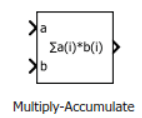
To add a block to a model, double-click the canvas and start typing the block name. Then, select the block from the list.
Libraries:
HDL Coder /
HDL Operations
Description
The Multiply-Accumulate block computes the product of inputs a, b, and adds a bias value c to produce dataOut.
dataOut = sum(a.* b) + c
The block uses the Operation Mode parameter to control how it
performs accumulation. With Operation Mode set to
Vector, the block computes the dot product of values at
the input ports a, b, then adds the bias
value c. By default, the bias value c is
0. To use a nonzero bias value, set Bias to
Dialog or Input port. The block performs
multiplication in full precision regardless of the Output data type
setting. The Output data type and Integer rounding
mode settings apply to the addition operation. To generate HDL code for
the block, use vector inputs. For scalar inputs, use the Multiply-Add block.
When Operation Mode is set to Streaming - using
Start and End ports or Streaming - using Number of
Samples, the block uses control signals to indicate when accumulation
starts, when accumulation ends, and when the output is valid. Use Streaming -
using Start and End ports when you want control signals to define the
accumulation interval. Use Streaming - using Number of Samples when
you want the block to accumulate a fixed number of valid samples.
Ports
Input
Output
Parameters
Specify how the block performs accumulation.
When Operation Mode is set to
Vector, the block performs the dot product of the values at the input ports a and b and adds the value at port c to produce the result.When Operation Mode is set to
Streaming - using Start and End ports, the block accumulates scalar input samples over a frame defined by control signals.When Operation Mode is set to
Streaming - using Number of
                Samples
, the block accumulates a specified number of valid scalar input samples.
Programmatic Use
Block parameter:
opMode |
| Type: character vector |
Value:
'Vector' | 'Streaming - using Start and
End ports' | 'Streaming - using Number of
Samples' |
Default:
'Vector' |
Specify how the block gets the bias or initial accumulator value.
When Bias is set to
Dialog, the block uses the value specified by Initial valueWhen Bias is set to
Input port, the block uses input port c.
Programmatic Use
Each operating mode uses a separate set of parameters for bias source and value:
Vector mode:
Block parameter (source):
initValueSetting |
| Type: character vector |
Value:
'Dialog' | 'Input
port' |
Default:
'Dialog' |
Block parameter (value):
initValue |
| Type: character vector |
| Value: A scalar number |
Default:
'0' |
Streaming - using Start and End ports mode:
Block parameter (source):
initValueSetting2 |
Block parameter (value):
initValue2 |
Streaming - using Number of Samples mode:
Block parameter (source):
initValueSetting3 |
Block parameter (value):
initValue3 |
Specify the Number of Samples to define a frame containing the number of samples of valid accumulated output dataOut.
Dependencies
To enable this port, set Operation Mode to
Streaming - using Number of
Samples.
Programmatic Use
Block parameter:
num_samples |
| Type: character vector |
| Value: A positive integer greater than zero |
Default:
'2' |
Set the output data type to:
A rule that inherits a data type, such as
Inherit: Same as first input.A built-in data type, such as
singleorint16.The name of a data type object. For instance, a
Simulink.NumericTypeobject.An expression that evaluates to a valid data type, for example,
fixdt(1,16,0)
The streaming modes do not support Inherit: Inherit via internal
rule. When you set the Output data type,
you can use the Data Type Assistant. To display the
assistant, click the Show data type assistant
 .
.
Programmatic Use
Block parameter:
OutDataTypeStr |
| Type: character vector |
Default:
'Inherit: Inherit via internal rule' |
To see possible values that you can specify for this parameter, see Programmatically Specify Block Parameters and Properties.
Specify the rounding mode that the block uses for fixed-point addition.
CeilingRounds positive and negative numbers toward positive infinity. Equivalent to the MATLAB®
ceilfunction.ConvergentRounds number to the nearest representable value. If a tie occurs, rounds to the nearest even integer. Equivalent to the Fixed-Point Designer™
convergentfunction.FloorRounds positive and negative numbers toward negative infinity. Equivalent to the MATLAB
floorfunction.NearestRounds the number to the nearest representable value. If a tie occurs, rounds toward positive infinity. Equivalent to the Fixed-Point Designer
nearestfunction.RoundRounds number to the nearest representable value. If a tie occurs, rounds positive numbers toward positive infinity and rounds negative numbers toward negative infinity. Equivalent to the Fixed-Point Designer
roundfunction.SimplestChooses between rounding toward floor and rounding toward zero to generate rounding code that is as efficient as possible.
ZeroRounds number toward zero. Equivalent to the MATLAB
fixfunction.
Programmatic Use
Each operating mode uses a separate rounding mode parameter:
Block parameter (Vector mode):
RndMeth |
Block parameter (Streaming - using Start
and End ports):
RndMeth2 |
Block parameter (Streaming - using Number
of Samples):
RndMeth3 |
| Type: character vector |
Values:
'Floor' | 'Ceiling' |
'Convergent' | 'Nearest'
| 'Round' | 'Simplest' |
'Zero' |
Default:
'Floor' |
To see possible values that you can specify for this parameter, see Programmatically Specify Block Parameters and Properties.
Specify how the block handles fixed-point overflow during accumulation.
 off (Wrap)
The block wraps the result on overflow. This mode is the most efficient for HDL code generation.
 on (Saturate)
The block saturates the result on overflow. When the result overflows, the block sets the output to the closest representable value.
Dependencies
To enable this parameter, set Operation Mode to
Vector.
Programmatic Use
Block parameter:
DoSatur |
| Type: character vector |
Values:
'off' | 'on' |
Default:
'off' |
Select this parameter to enable the validOut output port.
Dependencies
To enable this port, set Operation Mode to
Streaming - using Number of Samples or
Streaming - using Start and End
ports.
Programmatic Use
Block parameter:
validOut |
| Type: character vector |
Values:
'off' | 'on' |
Default:
'on' |
Select this parameter to enable the endIn input port and the endOut output port.
Dependencies
To enable this port, set Operation Mode to
Streaming - using Start and End
Ports.
Programmatic Use
Block parameter:
endInandOut |
| Type: character vector |
Values:
'off' | 'on' |
Default:
'on' |
Select this parameter to enable the startOut output port.
Dependencies
To enable this port, set Operation Mode to
Streaming - using Start and End
Ports.
Programmatic Use
Block parameter:
startOut |
| Type: character vector |
Values:
'off' | 'on' |
Default:
'on' |
Select this parameter to enable the countOut port.
Dependencies
To enable this port, set Operation Mode to
Streaming - using Number of
Samples.
Programmatic Use
Block parameter:
countOut |
| Type: character vector |
Values:
'off' | 'on' |
Default:
'on' |
Tips
With the Multiply-Accumulate block, you can:
Perform matrix multiplication operations. For example, if you have two matrix inputs with dimensions
N-by-MandM-by-P, you can compute the result by usingN-by-Pmultiply-accumulate operations in parallel.Replace a sequence of multiplication and addition operations, such as in filter blocks, and improve the performance on hardware by mapping to DSP slices on the FPGA. This figure shows how you can use the Multiply-Accumulate block with the
sfir_fixedmodel.
Algorithms
You can use the Operation Mode setting for the block to
specify a streaming mode of operation. When you select Streaming - using
Start and End Ports, you see three additional settings enabled by
default. The settings include:
Enable valid output port
Enable end input and output ports
Enable start output port
Leave these settings enabled. When you apply the settings, three additional input ports and three additional output ports appear:
| Input Ports | Output Ports |
|---|---|
| startIn | startOut |
| validIn | validOut |
| endIn | endOut |
This figure illustrates the streaming mode of operation using the start and end
ports. In this example, the bias value is 8.

Initially, when validIn is low, dataOut
is zero. At time 1s, both startIn and
validIn become high. Therefore,
validOut becomes high in the next clock cycle and
dataOut starts producing valid accumulation output. During
accumulation, dataOut takes the values of
a and b from the previous clock cycle.
For example, at time t = 2s, dataOut = 1*1 +
8 = 9.
To continue accumulation, make startIn low at the next clock cycle and keep validIn high. dataOut continues accumulating the inputs until validIn becomes low. At each time step, dataOut computes the product of the inputs from the previous clock cycle and sums the result with the dataOut value from the previous clock cycle. For example, at time t = 3s, dataOut = 2*2 + 9 = 13.
When validIn becomes low, dataOut holds the output value as seen at time t = 5s. At t = 5s, endIn and validIn are high. Therefore, endOut becomes high in the next clock cycle, which indicates end of frame. Therefore the frame between t = 2s (when startOut is high) and t = 6s (when endOut is high) indicates a frame containing valid output.
If startIn, validIn, and endIn are all high at the same time, only the dataOut corresponding to those inputs are accumulated as seen at t = 8s. If startIn is high for multiple clock cycles, and if validIn is high, the accumulator is reset at each clock cycle as seen at t = 10s and t = 11s. The accumulation continues at t = 12s.
You can use the Operation Mode setting for the block to
specify a streaming mode of operation. When you select Streaming - using
Number of Samples, you see two additional settings enabled by default.
The settings include:
Enable valid output port
Enable count output port
Leave these settings enabled. When you apply the settings, you have an additional input port validIn and three additional output ports appear:
endOut
validOut
countOut
This figure illustrates the streaming mode of operation using the number of
samples. In this example, the bias value is 8 and the
Number of Samples is 5.

Initially, when validIn is low, dataOut
is 0 and countOut is 1.
At time 1s, validIn becomes high. Therefore,
validOut becomes high in the next clock cycle, and
dataOut starts producing valid accumulation output. During
accumulation, dataOut takes the values of
a and b from the previous clock cycle.
For example, at time t = 2s, dataOut = 1*1 =
1. countOut increments by
1 at the next clock cycle, that is, at t =
3s, countOut becomes
2.
To continue accumulation, keep validIn high.
dataOut continues accumulating the inputs until
validIn becomes low. When five valid outputs are obtained
from dataOut, countOut becomes
5 and endOut becomes high, which
indicates the end of the frame. Therefore, the time between when
countOut is 1 and when
countOut is 5 indicates a frame containing valid
output.
The accumulator counter is now reset and countOut starts from
1. When validIn becomes high again,
dataOut starts accumulating a new set of values and
countOut starts incrementing for each valid
dataOut.

