Hierarchical Modeling Guidelines
Consider using these recommended settings when you build your model hierarchically and generate HDL code for your design. Each guideline has a severity level that indicates the level of compliance requirements. To learn more, see HDL Modeling Guidelines Severity Levels.
Avoid Constant Block Connections to Subsystem Port Boundaries
Guideline ID
1.2.4
Severity
Mandatory
Description
It is recommended that you avoid directly connecting Constant blocks to the output ports of a Subsystem. Synthesis tools may optimize and remove the constants and create unconnected ports.
If you use floating-point data types with the Native Floating Point mode enabled, and input constant values to an arithmetic operator such as an Add block, HDL Coder™ replaces the Add block with a Constant block when generating code. This optimization can result in a Constant block directly connected to the output port. Therefore, it is recommended that you avoid such modeling constructs. See also Simplify Constant Operations and Reduce Design Complexity in HDL Coder.
For example, open the model hdlcoder_constant_subsystem_boundary.slx. The DUT contains two subsystems Constant_subsys1 and Constant_subsys2, the outputs of which are inputs to a third Subsystem. Constant_subsys1 contains Constant blocks directly connected to the output ports, and Constant_subsys2 contains Constant blocks that have single data types as inputs to an Add block.
load_system('hdlcoder_constant_subsystem_boundary.slx')
set_param('hdlcoder_constant_subsystem_boundary','SimulationCommand','Update')
open_system('hdlcoder_constant_subsystem_boundary/DUT/Constant_subsys1')
open_system('hdlcoder_constant_subsystem_boundary/DUT/Constant_subsys2')
As Constant_subsys2 uses single data types and the model has Native Floating Point mode enabled, when you generate HDL code for the DUT, the Constant_subsys2 becomes a candidate for the optimization that simplifies constant operations. When you open the generated model, you see a Constant block directly connected to the output port.
open_system('gm_hdlcoder_constant_subsystem_boundary.slx')
set_param('gm_hdlcoder_constant_subsystem_boundary','SimulationCommand','Update')
open_system('gm_hdlcoder_constant_subsystem_boundary/DUT/Constant_subsys2')
Generate Parameterized HDL Code for Constant and Gain Blocks
Guideline ID
1.2.5
Severity
Recommended
Description
To generate parameterized HDL code for Gain and Constant blocks:
The Subsystem that contains the Gain and Constant blocks must be a masked subsystem. The Gain and Constant blocks use these mask parameter values. You define mask parameters of the Subsystem in the Mask Editor dialog box.
The Subsystem that contains the Gain and Constant blocks must be an Atomic Subsystem. To make a Subsystem an Atomic Subsystem, right-click that Subsystem and select Treat as atomic unit.
Enable the Generate parameterized HDL code from masked subsystem setting in the Configuration Parameters dialog box or set
MaskParameterAsGenerictoonat the command line usingmakehdlorhdlset_param. For more information, see Generate parameterized HDL code from masked subsystem.
For an example, open the model hdlcoder_masked_subsystems. The Top Subsystem contains two atomic masked subsystems MASKSUB and MASKSUB1 that are similar but for the masked parameter values.
load_system('hdlcoder_masked_subsystems')
set_param('hdlcoder_masked_subsystems', 'SimulationCommand', 'Update')
open_system('hdlcoder_masked_subsystems/TOP')
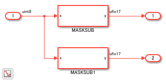
The model has the MaskParameterAsGeneric setting enabled. This setting corresponds to the Generate parameterized HDL code from masked subsystem setting that is enabled at the command line.
hdlsaveparams('hdlcoder_masked_subsystems')
%% Set Model 'hdlcoder_masked_subsystems' HDL parameters
hdlset_param('hdlcoder_masked_subsystems', 'HDLSubsystem', 'hdlcoder_masked_subsystems/TOP');
hdlset_param('hdlcoder_masked_subsystems', 'MaskParameterAsGeneric', 'on');
To generate VHDL® code for the Top Subsystem, run this command:
makehdl('hdlcoder_masked_subsystems/TOP')
In the generated code, you see that HDL Coder™ generates one HDL file MaskedSub with the different masked parameters mapped to generic ports.
-- -------------------------------------------------------------
--
-- File Name: hdlsrc\hdlcoder_masked_subsystems\TOP.vhd
-- Created: 2018-10-08 13:30:02
--
-- Generated by MATLAB 9.6 and HDL Coder 3.13
--
--
-- -------------------------------------------------------------
--
--

ARCHITECTURE rtl OF TOP IS

  -- Component Declarations
  COMPONENT MASKSUB
    GENERIC( m                            : integer;
             b                            : integer
             );
    PORT( x                               :   IN    std_logic_vector(7 DOWNTO 0);  -- uint8
          y                               :   OUT   std_logic_vector(16 DOWNTO 0)  -- ufix17
          );
  END COMPONENT;

  -- Component Configuration Statements
  FOR ALL : MASKSUB
    USE ENTITY work.MASKSUB(rtl);

  -- Signals
  SIGNAL MASKSUB_out1                     : std_logic_vector(16 DOWNTO 0);  -- ufix17
  SIGNAL MASKSUB1_out1                    : std_logic_vector(16 DOWNTO 0);  -- ufix17

BEGIN
  u_MASKSUB : MASKSUB
    GENERIC MAP( m => 5,
                 b => 2
                 )
    PORT MAP( x => In1,  -- uint8
              y => MASKSUB_out1  -- ufix17
              );

  u_MASKSUB1 : MASKSUB
    GENERIC MAP( m => 6,
                 b => 4
                 )
    PORT MAP( x => In1,  -- uint8
              y => MASKSUB1_out1  -- ufix17
              );

  Out1 <= MASKSUB_out1;

  Out2 <= MASKSUB1_out1;

END rtl;
Place Physical Signal Lines Inside a Subsystem
Guideline ID
1.2.6
Severity
Mandatory
Description
To avoid errors when generating HDL test bench, physical signal lines that are
present at the same level as the DUT subsystem must be placed inside a
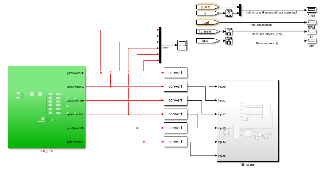
Subsystem block. For example, consider this Simulink® model that has physical signal lines outside the DUT subsystem,
HDL_DUT.

Place the physical signal lines and the blocks connected to it that are highlighted inside a Subsystem block. You can then generate HDL code and test bench for the DUT subsystem.