Verify Viterbi Decoder Using HDL Cosimulation
This example shows how to generate and verify HDL code to implement a fixed-point Viterbi decoder.
To run this example, in addition to the required MATLAB® products, you must install and include on the MATLAB system path either Siemens® ModelSim™/Questasim™ or Cadence® Xcelium™.
Overview of Simulink Model
Open the Simulink® model viterbi_codegen.slx. This model generates HDL code for a fixed-point Viterbi decoder.
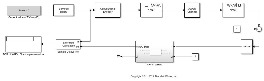
The model uses binary phase-shift keying (BPSK) and additive white Gaussian noise (AWGN) blocks to simulate the wireless transmission of data. In the top model, the parameter EsNo, which represents the average signal energy to noise ratio, affects the transmission of data. By default, the EsNo parameter is set to 0.
After you initiate the data transmission, the testbench feeds the data into the Viterbi Decoder (Wireless HDL Toolbox) block, which is implemented using the Wireless HDL Toolbox™ product. The Viterbi Decoder block attempts to recover the original data but might have errors in the recovery. To measure how accurate this decoder is, the testbench sends the decoded data to an Error Rate Calculation (Communications Toolbox) block along with the original data. Then the Display (Simulink) block displays the results from this calculation.
Generate HDL Code
To open the HDL Coder app, on the Apps tab in the Simulink Toolstrip, click the HDL Coder app icon. To select the toolchain you want to use for your cosimulation, first click Settings to open the Configurations Parameters dialog box. In the left pane, click HDL Code Generation, then Test Bench. For the Simulation tool parameter, select the toolchain. Apply the changes by clicking OK.
To generate HDL code for the Viterbi decoder and open a new Simulink model, click Generate Testbench, then HDL Cosimulation.
Launch HDL Simulator
You can connect and format the new Simulink model to accommodate your testbench. This example includes two prepared models: viterbi_modelsim.slx and viterbi_xcelium.slx. Choose the model that fits your toolchain. This example uses the ModelSim/QuestaSim Simulink model, which is shown in the figure.

To launch the HDL simulator, double-click the Start Simulator block in the model. In addition to launching the HDL simulator, this action inputs the commands to compile the HDL code and prepares for cosimulation with MATLAB and Simulink.
Run Simulation
When the HDL simulator finishes compiling the HDL files and preparing for simulation, the text Ready for cosimulation ... appears in the HDL simulator command window. After this text appears, return to the open model in Simulink and run the simulation from there.
When the simulation finishes, the Simulink model displays the results. In this example, the results are displayed as the bit error rate (BER) shown in the two Display blocks. The two displays show the BER results from the Viterbi Decoder block from the Wireless HDL Toolbox Product and the HDL coded block implemented using HDL Coder™. Based on the results, the HDL Coder implementation yields the same results as the original block.
Rerun Simulation with New Parameters
The parameter EsNo controls the behavior of the transmission. Change this parameter to change the simulation behavior. For example, enter this command at the MATLAB command prompt.
EsNo = 5;
Changing this parameter does not require new HDL code to be generated, as this change does not affect the Viterbi block. To repeat this example with the new parameter value, run the simulation again from the open Simulink model.
Finish Simulation
After you are finished with simulation, close the HDL simulator session. Then, return to Simulink and close the model.
See Also
makehdl (HDL Coder) | makehdltb (HDL Coder) | Viterbi
Decoder (Wireless HDL Toolbox)
Topics
- Set Up for HDL Cosimulation
- Run HDL Cosimulation from MATLAB
- Generate HDL Code (Wireless HDL Toolbox)
- Choose a Test Bench for Generated HDL Code (HDL Coder)