E-NTU Heat Transfer
Detailed heat transfer model between two general fluids

Libraries:
Simscape /
Fluids /
Heat Exchangers /
Fundamental Components
Description
The E-NTU Heat Transfer block models the heat exchange between two general fluids based on the standard Effectiveness-NTU method. The fluid thermal properties are specified explicitly through Simscape™ physical signals. Combine with the Heat Exchanger Interface (TL) or Heat Exchanger Interface (G) blocks to model the pressure drop and temperature change between the inlet and outlet of a heat exchanger.
The block dialog box provides a choice of common heat exchanger configurations. These include concentric-pipe with parallel and counter flows, shell-and-tube with one or more shell passes, and cross-flow with mixed and unmixed flows. A generic configuration lets you model other heat exchangers based on tabular effectiveness data.
Heat Exchanger Configurations
Heat Transfer Rate
The E-NTU model defines the heat transfer rate between fluids 1 and 2 in terms of an effectiveness parameter ε
where:
Q is the net heat transfer rate.
QMax is the maximum possible heat transfer rate between fluid 1 and fluid 2 at a given set of operating conditions.
ε is the effectiveness parameter.
If you clear the Enable wall thermal mass checkbox,
where Q1 and Q2 are the heat transfer rates into fluid 1 and fluid 2.
The maximum possible heat transfer rate between the two fluids is
where:
CMin is the minimum value of the thermal capacity rate:
T1,In and T2,In are the inlet temperatures of fluid 1 and fluid 2.
and are the mass flow rates of fluid 1 and fluid 2 into the heat exchanger volume through the inlet.
cp,1 and cp,2 are the specific heat coefficients at constant pressure of fluid 1 and fluid 2. The Minimum fluid-wall heat transfer coefficient parameter in the block dialog box sets a lower bound on the allowed values of the heat transfer coefficients.
The fluid properties that the block uses in heat transfer calculations are the average between the value at the inlet and the value in the fluid volume.
Heat Exchanger Effectiveness
The heat exchanger effectiveness calculations depend on the flow arrangement type
selected in the block dialog box. For all but Generic —
effectiveness table, the block computes the thermal exchange
effectiveness through analytical expressions written in terms of the number of
transfer units (NTU) and thermal capacity ratio. The number of transfer units is
defined as
where:
NTU is the number of transfer units.
UOverall is the overall heat transfer coefficient between fluid 1 and fluid 2.
ROverall is the overall thermal resistance between fluid 1 and fluid 2.
AHeat is aggregate area of the primary and secondary, or finned, heat transfer surfaces.
The thermal capacity ratio is defined as
where:
Crel is the thermal capacity ratio.
The overall heat transfer coefficient and thermal resistance used in the NTU calculation are functions of the heat transfer mechanisms at work. These mechanisms include convective heat transfer between the fluids and the heat exchanger interface and conduction through the interface wall [2]:
where:
U1 and U2 are the heat transfer coefficients between fluid 1 and the interface wall and between fluid 2 and the interface wall.
A1 and A2 are the heat transfer surface areas on the fluid-1 and fluid-2 sides.
RFoul,1 and RFoul,2 are the fouling resistances on the fluid-1 and fluid-2 sides. The fouling resistance is equal to the fouling factor parameter divided by the heat transfer surface area.
RWall is the interface wall thermal resistance.
Heat Transfer From Fluid 1 to Fluid 2
The tables show some of the analytical expressions used to compute the heat exchange effectiveness [1]. The parameter N refers to the number of shell passes and the parameter ε1 to the effectiveness for a single shell pass.
| Concentric Tubes | |
| Counter Flow |
|
| Parallel Flow |
|
| Shell and Tube | |
One shell pass and two, four, or six tube passes |
|
N Shell Passes and 2N, 4N, or 6N Tube Passes |
|
| Cross Flow (Single Pass) | |
| Both Fluids Unmixed |
|
| Both Fluids Mixed |
|
| CMax mixed, CMin unmixed |
|
| CMax unmixed, CMin mixed |
|
Wall Thermal Mass
If you select Enable wall thermal mass, the block models the heat exchanger wall thermal mass, which introduces a delay in the wall's transient response to changes in temperature or heat flux. If you model thermal mass, the wall stores heat in its bounds. This heat storage slows the transition between steady states so that a thermal perturbation on one side does not immediately manifest on the other side. The lag persists until the heat flow rates from the two sides balance.
If you select Enable wall thermal mass, the wall energy conservation is
where:
Mwall is the value of the Wall mass parameter.
cp,wall is the value of the Wall specific heat parameter.
Twall is the effective wall temperature on each side. The block uses this value to model the transient response. You cannot measure this value.
The heat transfer to each fluid is
where:
Tin is the fluid inlet temperature on each side.
C is the heat capacity rate for each fluid.
The number of heat transfer units between the fluid and the wall on each side is
where A is the wall surface area and U is the heat transfer coefficient.
Examples
This example compares heat transfer through two equivalent heat exchangers. One heat exchanger uses the Heat Exchanger (G-G) block and the other uses a combination of the E-NTU Heat Transfer and Heat Exchanger Interface (G) blocks.
The Heat Exchanger (G-G) block is a composite component made from two Heat Exchanger Interface (G) blocks and an E-NTU Heat Transfer block. The Heat Exchanger (G-G) block is equivalent to the second heat exchanger in this model, which explicitly uses two Heat Exchanger Interface (G) blocks and an E-NTU Heat Transfer Block.
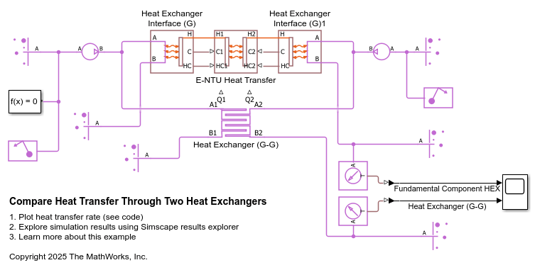
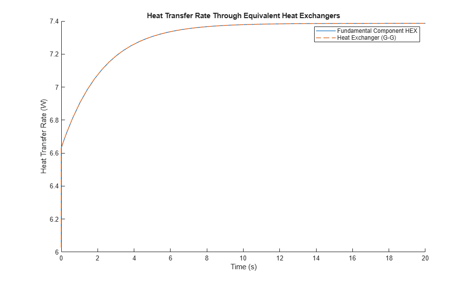
Because these heat exchangers are equivalent, they have the same characteristics. This figure shows that the rate of heat transfer through both heat exchangers is the same.
Assumptions and Limitations
The flows are single-phase.
The heat transfer is strictly one of sensible heat.
The transfer is limited to interior of the exchanger, with the environment neither gaining heat from nor providing heat to the flows. The heat exchanger is an adiabatic component.
Ports
Input
Conserving
Parameters
References
[1] Holman, J. P. Heat Transfer. 9th ed. New York, NY: McGraw Hill, 2002.
[2] Shah, R. K. and D. P. Sekulic. Fundamentals of Heat Exchanger Design. Hoboken, NJ: John Wiley & Sons, 2003.