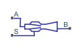
Jet Pump (IL)
Liquid-liquid jet pump in an isothermal liquid network
Libraries:
Simscape /
Fluids /
Isothermal Liquid /
Pumps & Motors
Description
The Jet Pump (IL) block models a liquid-liquid jet pump in an isothermal liquid network. The motive and suction fluids in the jet pump are the same. The motive fluid enters the primary nozzle at port A and draws in the suction fluid through input port S. After mixing in the throat, the combined flow expands through the diffuser and discharges at port B. The total pressure change over the pump is the sum of the individual contributions of friction and area change in each section of the pump and momentum changes in the throat. The sign convention for the equations correspond to positive flow into the throat.
Changes in Pressure Due to Area Changes
The mass flow rate is conserved in the pump
where A is the mass flow rate through port A, S is the mass flow rate through port S, and A is the mass flow rate through port B.
Using mass conservation and the Bernoulli Principle, you can express the area changes over the pump segments in terms of pressure change. The pressure change associated with the nozzle is
or 0, whichever is greater. AN is the value of the Nozzle exit area parameter and ρ is the fluid density.
The pressure change due to the area at the suction inlet is
or 0, whichever is greater. AT is the cross-sectional area of the throat. The pressure change over the diffuser expansion is
where a is the value of the Diffuser inlet to outlet area ratio parameter.
Reversed Flows
In the case of reversed flow, the block does not model the effect of the nozzle area on pressure change, and the flow traveling from the throat through the nozzle does not undergo any pressure gain. This behavior ensures the numerical stability of the block during simulation of reversed flows.
Changes in Pressure Due to Mixing
The motive and suction flows mix in the throat. The change in pressure from mixing is
where b is the value of the Nozzle exit to throat area ratio parameter, which is defined between the largest and smallest cross-sectional areas of the nozzle.
Pressure Losses Due to Friction
The flow loses pressure due to due to friction in the nozzle, secondary suction inlet, throat, and diffuser. The block calculates these losses based on a coefficient for each section and the area, or area ratio, between different sections of the pump. Friction causes pressure loss regardless of the flow direction. The pressure loss in the nozzle due to friction is
where KN is the value of the Primary flow nozzle loss coefficient parameter. The pressure loss due to friction in the suction flow through the annulus is
where KS is the value of the Secondary flow entry loss coefficient parameter. The pressure loss in the throat due to friction is
where KT is the value of the Throat loss coefficient parameter. The pressure loss in the diffuser due to friction is
where KD is the value of the Diffuser loss coefficient parameter. The sign corresponds to negative flow from the throat toward port B. Because the block defines losses for the regions of highest velocity in the flow, the block uses the throat area, which is equal to the diffuser inlet area, in the diffuser loss equation.
Saturation Pressure in the Nozzle
Cavitation occurs when a region of low pressure in the flow falls below the vapor saturation pressure, which creates pockets of vapor in the liquid and impedes any further increase in flow through the pump. You can model this flow rate limit by specifying a minimum nozzle pressure. If the flow pressure is more than the value of the Minimum allowable nozzle pressure parameter, the fluid velocity remains constant. Between the nozzle and the diffuser, the pressure change is either
or whichever is smaller.
The total pressure change in the nozzle is
The total pressure change in the annulus is
Assumptions and Limitations
The motive and suction liquids are the same.
Mixing in the throat is uniform and complete.
The nozzle inlet is much larger than the nozzle outlet, and the suction jet annulus is much smaller than the suction inlet.
For reversed flows, the block does not model change in pressure due to the nozzle.
The block models any effect of cavitation as a maximum limit on the flow rate in the throat.
Examples

Well with Jet Pump
A well jet pump installation. The well jet pump installation presented in this example consists of a surface-mounted centrifugal pump and a jet pump installed in the well below the surface of the water.
Ports
Conserving
Parameters
Extended Capabilities
Version History
Introduced in R2020a