Main Content

Pressure-Compensated Pump (IL)

Constant-pressure, variable-displacement pump in an isothermal liquid network

Since R2020a

  • Pressure-Compensated Pump (IL) block

Libraries:
Simscape / Fluids / Isothermal Liquid / Pumps & Motors

Description

The Pressure-Compensated Pump (IL) block models a constant-pressure, variable-displacement pump in an isothermal liquid network. The pump displacement is controlled by the differential pressure, pcontrol, measured between ports X and Y. When this pressure exceeds the Set pressure differential, the fluid displacement is adjusted according to the pump Leakage and friction parameterization. The variable-displacement functionality occurs within the Pressure regulation range between the Maximum displacement, at pset, and the Minimum displacement, at pmax.

The fluid may move from port A to port B, called forward mode, or from port B to port A, called reverse mode. Pump mode operation occurs when there is a pressure gain in the direction of the flow. Motor mode operation occurs when there is a pressure drop in the direction of the flow.

Shaft rotation corresponds to the sign of the fluid volume moving through the pump. Positive fluid displacement corresponds to positive shaft rotation in forward mode. Negative fluid displacement corresponds to negative shaft angular velocity in forward mode.

Operation Modes

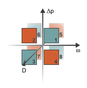
The block has eight modes of operation. The working mode depends on the pressure gain from port A to port B, Δp = pBpA; the angular velocity, ω = ωRωC; and the fluid volumetric displacement, set by the pressure differential. The figure above maps these modes to the octants of a Δp-ω-D chart:

  • Mode 1, Forward Pump: Positive shaft angular velocity causes a pressure increase from port A to port B and flow from port A to port B.

  • Mode 2, Reverse Motor : Flow from port B to port A causes a pressure decrease from B to A and negative shaft angular velocity.

  • Mode 3, Reverse Pump: Negative shaft angular velocity causes a pressure increase from port B to port A and flow from B to A.

  • Mode 4, Forward Motor: Flow from port A to B causes a pressure decrease from A to B and positive shaft angular velocity.

  • Mode 5, Reverse Motor : Flow from port B to port A causes a pressure decrease from B to A and positive shaft angular velocity.

  • Mode 6, Forward Pump: Negative shaft angular velocity causes pressure increase from A to B and flow from A to B.

  • Mode 7, Forward Motor: Flow from port A to B causes a pressure decrease from A to B and negative shaft angular velocity.

  • Mode 8, Reverse Pump: Positive shaft angular velocity causes a pressure increase from port B to port A and flow from B to A.

The block has analytical, lookup table, and physical signal parameterizations. When using tabulated data or an input signal for parameterization, you can choose to characterize pump operation based on efficiency or losses.

The threshold parameters Pressure gain threshold for pump-motor transition, Angular velocity threshold for pump-motor transition, and Displacement threshold for pump-motor transition identify regions where numerically smoothed flow transition between the pump operational modes can occur. For the pressure and angular velocity thresholds, choose a transition region that provides some margin for the transition term, but which is small enough relative to the typical pump pressure gain and angular velocity so that it will not impact calculation results. For the displacement threshold, choose a threshold value that is smaller than the typical displacement volume during normal operation.

Analytical Leakage and Friction Parameterization

If you set Leakage and friction parameterization to Analytical, the block calculates leakage and friction from constant values for shaft velocity, pressure gain, and torque. The leakage flow rate, which is correlated with the pressure differential over the pump, is calculated as:

m˙leak=KρavgΔp,

where:

  • Δpnom is pBpA.

  • ρavg is the average fluid density.

  • K is the Hagen-Poiseuille coefficient for analytical loss,

    K=Dnomωnom(1ηv,nom)Δpnom,

    where:

    • Dnom is the Nominal displacement.

    • ωnom is the Nominal shaft angular velocity.

    • ηnom is the Volumetric efficiency at nominal conditions.

    • Δpnom is the Nominal pressure gain.

The friction torque, which is related to the pump pressure differential, is calculated as:

τfr=(τ0+k|ΔpDDnom|)tanh(4ω5×10⁵ωnom),

where:

  • τ0 is the No-load torque.

  • k is the friction torque vs. pressure gain coefficient at nominal displacement, which is determined from the Mechanical efficiency at nominal conditions, ηm,nom:

    k=τfr,nomτ0Δpnom.

    τfr,nom is the friction torque at nominal conditions:

    τfr,nom=(1ηm,nomηm,nom)DnomΔpnom.

  • ω is the relative shaft angular velocity, or ωRωC.

Tabulated Data Parameterizations

When using tabulated data for pump efficiencies or losses, you can provide data for one or more of the pump operational modes. The signs of the tabulated data determine the operational regime of the block. When data is provided for less than eight operational modes, the block calculates the complementing data for the other mode(s) by extending the given data into the remaining octants.

The Tabulated data - volumetric and mechanical efficiencies parameterization

The leakage flow rate is calculated as:

m˙leak=m˙leak,pump(1+α2)+m˙leak,motor(1α2),

where:

  • m˙leak,pump=(1ηυ)m˙ideal

  • m˙leak,motor=(ηv1)m˙

and ηv is the volumetric efficiency, which is interpolated from the user-provided tabulated data. The transition term, α, is

α=tanh(4ΔpΔpthreshold)tanh(4ωωthreshold)tanh(4DDthreshold),

where:

  • Δp is pBpA.

  • pthreshold is the Pressure gain threshold for pump-motor transition.

  • ω is ωRωC.

  • ωthreshold is the Angular velocity threshold for pump-motor transition.

The friction torque is calculated as:

τfr=τfr,pump(1+α2)+τfr,motor(1α2),

where:

  • τfr,pump=(1ηm)τ

  • τfr,motor=(ηm1)τideal

and ηm is the mechanical efficiency, which is interpolated from the user-provided tabulated data.

The Tabulated data - volumetric and mechanical losses parameterization

The leakage flow rate is calculated as:

m˙leak=ρavgqloss(Δp,ω,D),

where qloss is interpolated from the Volumetric loss table, q_loss(dp,w,D) parameter, which is based on user-supplied data for pressure gain, shaft angular velocity, and fluid volumetric displacement.

The shaft friction torque is calculated as:

τfr=τloss(Δp,ω,D),

where τloss is interpolated from the Mechanical loss table, torque_loss(dp,w,D) parameter, which is based on user-supplied data for pressure gain, shaft angular velocity, and fluid volumetric displacement.

Input Signal Parameterization

When you select Input signal - volumetric and mechanical efficiencies, ports EV and EM are enabled. The internal leakage and shaft friction are calculated in the same way as the Tabulated data - volumetric and mechanical efficiencies parameterization, except that ηv and ηm are received directly at ports EV and EM, respectively.

When you select Input signal - volumetric and mechanical losses, ports LV and LM are enabled. These ports receive leakage flow and friction torque as positive physical signals. The leakage flow rate is calculated as:

m˙leak=ρavgqLVtanh(4Δppthresh),

where:

  • qLV is the leakage flow received at port LV.

  • pthresh is the Pressure gain threshold for pump-motor transition parameter.

The friction torque is calculated as:

τfr=τLMtanh(4ωωthresh),

where

  • τLM is the friction torque received at port LM.

  • ωthresh is the Angular velocity threshold for pump-motor transition parameter.

The volumetric and mechanical efficiencies range between the user-defined specified minimum and maximum values. Any values lower or higher than this range will take on the minimum and maximum specified values, respectively.

Pump Operation

The pump flow rate is:

m˙=m˙idealm˙leak,

where m˙ideal=ρavgDω.

The pump torque is:

τ=τideal+τfr,

where τideal=DΔp.

The mechanical power delivered by the pump shaft is:

φmech=τω,

and the pump hydraulic power is:

φhyd=Δpm˙ρavg.

To be notified if the block is operating beyond the supplied tabulated data, set Check if operating beyond the range of supplied tabulated data to Warning to receive a warning if this occurs, or Error to stop the simulation when this occurs. For parameterization by input signal for volumetric or mechanical losses, you can be notified if the simulation surpasses operating modes with the Check if operating beyond pump mode parameter.

You can also monitor pump functionality. Set Check if pressures are less than pump minimum pressure to Warning to receive a warning if this occurs, or Error to stop the simulation when this occurs.

Displacement Parameterization

The linear parameterization of the pump displacement is:

D=p^(DminDmax)+Dmax,

where the normalized pressure, p^, is

p^=pcontrolpsetpmaxpset.

where pmax is the sum of the Set pressure differential and the Pressure regulation range.

Displacement Dynamics

If displacement dynamics are modeled, a lag is introduced to the flow response to the modeled control pressure. pcontrol becomes the dynamic control pressure, pdyn; otherwise, pcontrol is the steady-state pressure. The instantaneous change in dynamic control pressure is calculated based on the Time constant, τ:

p˙dyn=pcontrolpdynτ.

By default, Displacement dynamics is set to Off.

Numerically-Smoothed Pressure

You can maintain numerical robustness in your simulation by adjusting the Smoothing factor parameter. If the Smoothing factor parameter is nonzero, the block smoothly saturates the normalized control pressure between pset and pmax. For more information, see Numerical Smoothing.

Ports

Conserving

expand all

Entry or exit port of the liquid to or from the pump.

Entry or exit port of the liquid to or from the pump.

Control pressure in units of MPa, denoted Px. The control pressure, PxPy, is compared against the Set pressure differential to trigger or moderate variable pump displacement.

Control pressure in units of MPa, denoted Py. The control pressure, PxPy, is compared against the Set pressure differential to trigger or moderate variable pump displacement.

Rotating shaft angular velocity and torque.

Pump casing reference angular velocity and torque.

Pump efficiency for fluid displacement, specified as a physical signal. The value must be between 0 and 1.

Dependencies

To enable this port, set Leakage and friction parameterization to Input signal - volumetric and mechanical efficiencies.

Pump efficiency for the mechanical supply of energy, specified as a physical signal. The value must be between 0 and 1.

Dependencies

To enable this port, set Leakage and friction parameterization to Input signal - volumetric and mechanical efficiencies.

Pump losses associated with fluid displacement in m3/s, specified as a physical signal.

Dependencies

To enable this port, set Leakage and friction parameterization to Input signal - volumetric and mechanical losses.

Pump losses associated with the mechanical supply of energy in N*m, specified as a physical signal.

Dependencies

To enable this port, set Leakage and friction parameterization to Input signal - volumetric and mechanical losses.

Parameters

expand all

Pump

Parameterization of the leakage and friction characteristics of the pump.

  • In the Analytical parameterization, the leakage flow rate and the friction torque are calculated by analytical equations.

  • In the Tabulated data - volumetric and mechanical efficiencies parameterization, the volumetric and mechanical efficiencies are calculated from the user-supplied Pressure gain vector, dp, Shaft angular velocity vector, w, and Displacement vector, D parameters and interpolated from the 3-D Volumetric efficiency table, e_v(dp,w,D) and Mechanical efficiency table, e_m(dp,w,D) tables.

  • In the Tabulated data - volumetric and mechanical losses parameterization, the leakage flow rate and friction torque are calculated from the user-supplied Pressure gain vector, dp, Shaft angular velocity vector, w, and Displacement vector, D parameters and interpolated from the 3-D Volumetric loss table, q_loss(dp,w,D) and Mechanical loss table, torque_loss(dp,w,D) parameters.

  • In the Input signal - volumetric and mechanical efficiencies parameterization, the volumetric and mechanical efficiencies are received as physical signals at ports EV and EM, respectively.

  • In the Input signal - volumetric and mechanical loss parameterization, the leakage flow rate and friction torque are received as physical signals at ports LV and LM, respectively.

Amount of fluid displaced by shaft rotating under nominal operating conditions.

Dependencies

To enable this parameter, set Leakage and friction parameterization to Analytical.

Angular velocity of the shaft under nominal operating conditions.

Dependencies

To enable this parameter, set Leakage and friction parameterization to Analytical.

Pump pressure gain between the fluid entry and exit under nominal operating conditions.

Dependencies

To enable this parameter, set Leakage and friction parameterization to Analytical.

Ratio of actual flow rate to ideal flow rate at nominal conditions.

Dependencies

To enable this parameter, set Leakage and friction parameterization to Analytical.

Minimum value of torque to overcome seal friction and induce shaft motion.

Dependencies

To enable this parameter, set Leakage and friction parameterization to Analytical.

Ratio of actual mechanical power to ideal mechanical power at nominal conditions.

Dependencies

To enable this parameter, set Leakage and friction parameterization to Analytical.

Vector of pressure differential values for the tabular parameterization of leakage and torque friction. This vector forms an independent axis with the Shaft angular velocity vector, w and the Displacement vector, D parameters for the 3-D dependent Volumetric efficiency table, e_v(dp,w,D) and Mechanical efficiency table, e_m(dp,w,D) parameters. The vector elements must be listed in ascending order.

Dependencies

To enable this parameter, set Leakage and friction parameterization to either:

  • Tabulated data - volumetric and mechanical efficiencies

  • Tabulated data - volumetric and mechanical losses

Vector of angular velocity data for the tabular parameterization of leakage and torque friction. This vector forms an independent axis with the Pressure gain vector, dp and the Displacement vector, D parameters for the 3-D dependent Volumetric efficiency table, e_v(dp,w,D) and Mechanical efficiency table, e_m(dp,w,D) parameters. The vector elements must be listed in ascending order.

Dependencies

To enable this parameter, set Leakage and friction parameterization to either:

  • Tabulated data - volumetric and mechanical efficiencies

  • Tabulated data - volumetric and mechanical losses

Vector of fluid volumetric displacement data for the tabular parameterization of leakage and torque friction. This vector forms an independent axis with the Shaft angular velocity vector, w and the Pressure gain vector, dp parameters for the 3-D dependent Volumetric efficiency table, e_v(dp,w,D) and Mechanical efficiency table, e_m(dp,w,D) parameters. The vector elements must be listed in ascending order.

Dependencies

To enable this parameter, set Leakage and friction parameterization to either:

  • Tabulated data - volumetric and mechanical efficiencies

  • Tabulated data - volumetric and mechanical losses

M-by-N-by-P matrix of volumetric efficiencies at the specified fluid pressure gain, shaft angular velocity, and volumetric displacement. Linear interpolation is employed between table elements. M, N, and P are the sizes of the corresponding vectors:

  • M is the number of vector elements in the Pressure gain vector, dp parameter.

  • N is the number of vector elements in the Shaft angular velocity vector, w parameter.

  • P is the number of vector elements in the Displacement vector, D parameter.

Dependencies

To enable this parameter, set Leakage and friction parameterization to Tabulated data - volumetric and mechanical efficiencies.

M-by-N-by-P matrix of mechanical efficiencies at the specified fluid pressure gain, shaft angular velocity, and displacement. Linear interpolation is employed between table elements. M, N, and P are the sizes of the corresponding vectors:

  • M is the number of vector elements in the Pressure gain vector, dp parameter.

  • N is the number of vector elements in the Shaft angular velocity vector, w parameter.

  • P is the number of vector elements in the Displacement vector, D parameter.

Dependencies

To enable this parameter, set Leakage and friction parameterization to Tabulated data - volumetric and mechanical efficiencies.

M-by-N-by-P matrix of volumetric leakage at the specified fluid pressure gain, shaft angular velocity, and displacement. Linear interpolation is employed between table elements. M, N, and P are the sizes of the corresponding vectors:

  • M is the number of vector elements in the Pressure gain vector, dp parameter.

  • N is the number of vector elements in the Shaft angular velocity vector, w parameter.

  • P is the number of vector elements in the Displacement vector, D parameter.

Dependencies

To enable this parameter, set Leakage and friction parameterization to Tabulated data - volumetric and mechanical loss.

M-by-N-by-P matrix of friction torque at the specified fluid pressure gain, shaft angular velocity, and displacement. Linear interpolation is employed between table elements. M, N, and P are the sizes of the corresponding vectors:

  • M is the number of vector elements in the Pressure gain vector, dp parameter.

  • N is the number of vector elements in the Shaft angular velocity vector, w parameter.

  • P is the number of vector elements in the Displacement vector, D parameter.

Dependencies

To enable this parameter, set Leakage and friction parameterization to Tabulated data - volumetric and mechanical loss.

Minimum value of volumetric efficiency. If the input signal is below this value, the volumetric efficiency is set to the minimum volumetric efficiency.

Dependencies

To enable this parameter, set Leakage and friction parameterization to Input signal - volumetric and mechanical efficiencies.

Maximum value of volumetric efficiency. If the input signal is above this value, the volumetric efficiency is set to the maximum volumetric efficiency.

Dependencies

To enable this parameter, set Leakage and friction parameterization to Input signal - volumetric and mechanical efficiencies.

Minimum value of mechanical efficiency. If the input signal is below this value, the mechanical efficiency is set to the minimum mechanical efficiency.

Dependencies

To enable this parameter, set Leakage and friction parameterization to Input signal - volumetric and mechanical efficiencies.

Maximum value of mechanical efficiency. If the input signal is above this value, the mechanical efficiency is set to the maximum mechanical efficiency.

Dependencies

To enable this parameter, set Leakage and friction parameterization to Input signal - volumetric and mechanical efficiencies.

Threshold pressure gain value for the transition between pump and motor functionality. A transition region is defined around 0 MPa between the positive and negative values of the pressure gain threshold. Within this transition region, the computed leakage flow rate and friction torque are adjusted according to the transition term α to ensure smooth transition from one mode to the other.

Dependencies

To enable this parameter, set Leakage and friction parameterization to either:

  • Tabulated data - volumetric and mechanical efficiencies

  • Input signal - volumetric and mechanical efficiencies

  • Input signal - volumetric and mechanical losses

Threshold angular velocity value for the transition between motor and pump functionality. A transition region is defined around 0 rpm between the positive and negative values of the angular velocity threshold. Within this transition region, the computed leakage flow rate and friction torque are adjusted according to the transition term α to ensure smooth transition from one mode to the other.

Dependencies

To enable this parameter, set Leakage and friction parameterization to:

  • Tabulated data - volumetric and mechanical efficiencies

  • Input signal - volumetric and mechanical efficiencies

  • Input signal - volumetric and mechanical loss

Whether to notify if the extents of the supplied data are surpassed. Select Warning to be notified when the block uses values beyond the supplied data range. Select Error to stop the simulation when the block uses values beyond the supplied data range.

Dependencies

To enable this parameter, set Leakage and friction parameterization to:

  • Tabulated data - volumetric and mechanical efficiencies

  • Tabulated data - volumetric and mechanical losses

Whether to notify if block operates outside of the pump mode functionality. Select Warning to be notified when the block operates in the forward or reverse motor modes. Select Error to stop the simulation when the block operates in the forward or reverse motor modes.

Dependencies

To enable this parameter, set Leakage and friction parameterization to Input signal - volumetric and mechanical losses.

Whether to notify if the fluid at port A or B experiences low pressure. Select Warning to be notified when the outlet pressure falls below a minimum specified value. Select Error to stop the simulation when the outlet pressure falls below a minimum specified value.

The parameter helps to identify potential conditions for cavitation, when the fluid pressure falls below the fluid vapor pressure.

Lower threshold of acceptable pressure at the pump inlet or outlet.

Dependencies

To enable this parameter, set Check if pressures are less than pump minimum pressure to:

  • Warning

  • Error

Pressure Compensation

Upper limit to pump displacement.

Lower limit to pump displacement.

Threshold value beyond which pump displacement is adjusted.

Variable-displacement operational range. The pump operates between the Set pressure differential and the pump maximum pressure, which is pset + pregulation.

Whether to account for transient effects to the fluid system due to changes in pump fluid displacement. Setting Displacement dynamics to On approximates the condition change by introducing a first-order lag in the flow response. The magnitude of the Time constant also impacts the modeled displacement dynamics.

Constant that captures the time required for the fluid to reach steady-state when changing the fluid displacement. This parameter impacts the modeled displacement dynamics.

Extended Capabilities

C/C++ Code Generation
Generate C and C++ code using Simulink® Coder™.

Version History

Introduced in R2020a

expand all