Specific Dissipation Heat Exchanger Interface (G)
Thermal interface between a gas and its surroundings
Libraries:
Simscape /
Fluids /
Heat Exchangers /
Fundamental Components
Description
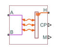
The Specific Dissipation Heat Exchanger Interface (G) block models the pressure drop and temperature change in a gas as it traverses the length of a thermal interface such as that provided by a heat exchanger. Heat transfer across the thermal interface is ignored. See the composite block diagram of the Heat Exchanger (G-G) block for an example showing how to combine the two blocks.
The pressure drop is calculated as a function of mass flow rate from tabulated data specified at some reference pressure and temperature. The calculation is based on linear interpolation if the mass flow rate is within the bounds of the tabulated data and on nearest-neighbor extrapolation otherwise. In other words, neighboring data points connect through straight-line segments, with those at the mass flow rate bounds extending horizontally outward.
The left figure demonstrates linear interpolation and the right demonstrates nearest-neighbor extrapolation.

The block calculations rely on the states and properties of the fluid temperature, density, and specific internal energy at the entrance to the thermal interface. The entrance changes abruptly from one port to the other during flow reversal, introducing discontinuities in the values of these variables. To eliminate these discontinuities, the block smooths the affected variables at mass flow rates below a specified threshold value.

Mass Balance
Mass can enter and exit the thermal interface through ports A andB. When you select Enable dynamic compressibility, the mass balance is
where:
M is the mass of the internal fluid volume of the thermal interface.
p is the internal fluid pressure.
T is the internal fluid temperature.
* are the mass flow rates in through the gas ports.
When you clear the Enable dynamic compressibility checkbox, the mass balance is
Energy Balance
Energy can enter and exit the thermal interface in two ways: with fluid flow through ports A and B and with heat flow through port H. When you select Enable dynamic compressibility, the energy balance is
where:
E is the total energy in the internal fluid volume of the thermal interface.
ϕ* are the energy flow rates in through the gas ports.
Q is the heat flow rate in through the thermal port.
If you clear the Enable dynamic compressibility checkbox, the energy balance is
where the total internal energy is
The block calculates the constant ρ0 from the Nominal liquid temperature and Nominal liquid pressure parameters.
Momentum Balance
The pressure drop calculation is based entirely on tabulated data that you specify. The causes of the pressure drop are ignored, except in the effects that they might have on the specified data. The overall pressure drop from one gas port to the other is calculated from the individual pressure drops from each gas port to the internal fluid volume:
where:
p* are the fluid pressures at the gas ports.
Δp* are the pressure drops from the gas ports to the internal fluid volume:
with p as the pressure in the internal fluid volume.
The tabulated data is specified at a reference pressure and temperature from which a third reference parameter, the reference density, is calculated. The ratio of the reference density to the actual port density serves as a correction factor in the individual pressure drop equations, each defined as:
where:
Δp() is the tabulated pressure drop function.
ρ* are the fluid densities at the gas ports.
The asterisk denotes the gas port (A or B) at which a parameter or variable is defined. Subscript R denotes a reference value. The density at the interface entrance is smoothed below the mass flow rate threshold by introducing a hyperbolic term ɑ:
where ρsmooth is the smoothed density at the entrance port, ρ* is the unsmoothed density at the same port, and ρ is the density in the internal fluid volume. The hyperbolic smoothing term is defined as:
where avg is the average of the mass flow rates through the gas ports and th is the mass flow rate threshold specified in the block dialog box. This threshold determines the width of the mass flow rate region over which to smooth the fluid density. The average mass flow rate is defined as: