Heat Exchanger (G-G)
Heat exchanger for systems with two gas flows
Libraries:
Simscape /
Fluids /
Heat Exchangers /
Gas
Description
The Heat Exchanger (G-G) block models a gas-gas heat exchanger. The wall can store heat in its bounds, adding to the heat transfer a slight transient delay that scales in proportion to its thermal mass. The fluids are single phase and each is a gas. Neither fluid can switch phase and so, as latent heat is never released, the exchange is strictly one of sensible heat.
Heat Transfer Model
The block heat transfer model derives from the Effectiveness-NTU method. Heat transfer in the steady state then proceeds at a fraction of the ideal rate which the flows, if kept each at its inlet temperature, and if cleared of every thermal resistance in between, could in theory support:
where Q the actual heat transfer rate, QMax is the ideal heat transfer rate, and ε is the fraction of the ideal rate actually observed in a real heat exchanger encumbered with losses. The fraction is the heat exchanger effectiveness, and it is a function of the number of transfer units, or NTU, a measure of the ease with which heat moves between flows, relative to the ease with which the flows absorb that heat:
where the fraction is the overall thermal conductance between the flows and CMin is the smallest of the heat capacity rates from among the flows that belonging to the flow least capable of absorbing heat. The heat capacity rate of a flow depends on the specific heat of the fluid (cp) and on its mass flow rate through the exchanger ():
The effectiveness depends also on the relative disposition of the flows, the number of passes between them, and the mixing condition for each. This dependence reflects in the effectiveness expression used, with different flow arrangements corresponding to different expressions. For a list of the effectiveness expressions, see the E-NTU Heat Transfer block.
The fluid properties that the block uses in heat transfer calculations are the average between the value at the inlet and the value in the fluid volume.
Flow Arrangement
Use the Flow arrangement block parameter to set how the flows meet in the heat exchanger. The flows can run parallel to each other, counter to each other, or across each other. They can also run in a pressurized shell, one through tubes enclosed in the shell, the other around those same tubes. The figure shows an example. The tube flow can make one pass through the shell flow (shown right) or, for greater exchanger effectiveness, multiple passes (left).
Other flow arrangements are possible through a generic parameterization based on tabulated effectiveness data and requiring little detail about the heat exchanger. Flow arrangement, mixing condition, and number of shell or tube passes, if relevant to the heat exchanger, are assumed to manifest in the tabulated data.
Mixing Condition
Use the Cross flow type parameter to mix each of the flows, one of the flows, or none of the flows. Mixing in this context is the lateral movement of fluid in channels that have no internal barriers, normally guides, baffles, fins, or walls. Such movement serves to even out temperature variations in the transverse plane. Mixed flows have variable temperature in the longitudinal plane alone. Unmixed flows have variable temperature in both the transverse and longitudinal planes. The figure shows a mixed flow (i) and an unmixed flow (ii).
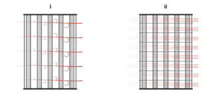
The distinction between mixed and unmixed flows is considered only in cross flow arrangements. There, longitudinal temperature variation in one fluid produces transverse temperature variation in the second fluid that mixing can even out. In counter and parallel flow arrangements, longitudinal temperature variation in one fluid produces longitudinal temperature variation in the second fluid and mixing, as it is of little effect here, is ignored.
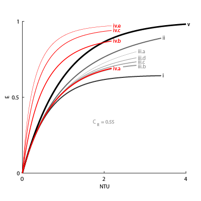
Effectiveness Curves
Shell-and-tube exchangers with multiple passes (iv.b-e in the figure for 2, 3, and 4 passes) are most effective. Of exchangers with a single pass, those with counter flows (ii are most effective and those with parallel flows (i) are least.
Cross-flow exchangers are intermediate in effectiveness, with mixing condition playing a factor. They are most effective when both flows are unmixed (iii.a) and least effective when both flows are mixed (iii.b). Mixing just the flow with the smallest heat capacity rate (iii.c) lowers the effectiveness more than mixing just the flow with the largest heat capacity rate (iii.d).
Thermal Resistance
The overall thermal resistance, R, is the sum of the local resistances lining the heat transfer path. The local resistances arise from convection at the surfaces of the wall, conduction through the wall, and, if the wall sides are fouled, conduction through the layers of fouling. Expressed in order from gas side 1 to gas side 2:
where U is the convective heat transfer coefficient, F is the fouling factor, and A is the heat transfer surface area, each for the flow indicated in the subscript. RW is the thermal resistance of the wall.
The wall thermal resistance and fouling factors are simple constants obtained from block parameters. The heat transfer coefficients are elaborate functions of fluid properties, flow geometry, and wall friction, and derive from standard empirical correlations between Reynolds, Nusselt, and Prandtl numbers. The correlations depend on flow arrangement and mixing condition, and are detailed for each in the E-NTU Heat Transfer block on which the block model is based.
Wall Thermal Mass
If you select Enable wall thermal mass, the block models the heat exchanger wall thermal mass, which introduces a delay in the wall's transient response to changes in temperature or heat flux. If you model thermal mass, the wall stores heat in its bounds. This heat storage slows the transition between steady states so that a thermal perturbation on one side does not immediately manifest on the other side. The lag persists until the heat flow rates from the two sides balance.
If you select Enable wall thermal mass, the wall energy conservation is
where:
Mwall is the value of the Wall mass parameter.
cp,wall is the value of the Wall specific heat parameter.
Twall is the effective wall temperature on each side. The block uses this value to model the transient response. You cannot measure this value.
The heat transfer to each fluid is
where:
Tin is the fluid inlet temperature on each side.
C is the heat capacity rate for each fluid.
The number of heat transfer units between the fluid and the wall on each side is
where A is the wall surface area and U is the heat transfer coefficient.
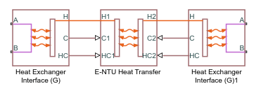
Composite Structure
The block is a composite component built from simpler blocks. A Heat Exchanger Interface (G) block models the gas flow on side 1 of the heat exchanger. Another models the gas flow on side 2. An E-NTU Heat Transfer block models the heat exchanged across the wall between the flows.
Examples
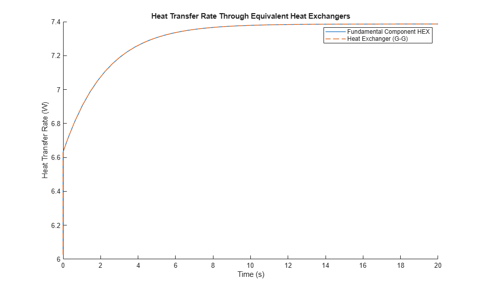
This example compares heat transfer through two equivalent heat exchangers. One heat exchanger uses the Heat Exchanger (G-G) block and the other uses a combination of the E-NTU Heat Transfer and Heat Exchanger Interface (G) blocks.
The Heat Exchanger (G-G) block is a composite component made from two Heat Exchanger Interface (G) blocks and an E-NTU Heat Transfer block. The Heat Exchanger (G-G) block is equivalent to the second heat exchanger in this model, which explicitly uses two Heat Exchanger Interface (G) blocks and an E-NTU Heat Transfer Block.
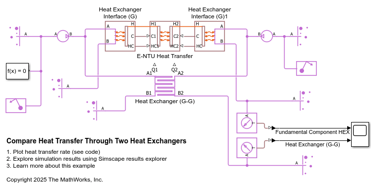
Because these heat exchangers are equivalent, they have the same characteristics. This figure shows that the rate of heat transfer through both heat exchangers is the same.