HARQ Indicator (HI) Channel
LTE uses a hybrid automatic repeat request (HARQ) scheme for error correction. The eNodeB sends a HARQ indicator to the UE to indicate a positive acknowledgment (ACK) or negative acknowledgment (NACK) for data sent using the uplink shared channel. The channel coded HARQ indicator codeword is transmitted through the Physical Hybrid Automatic Repeat Request Indicator Channel (PHICH).
HARQ Indicator
A HARQ indicator of ‘0’ represents a NACK and a ‘1’ represents an ACK.
PHICH Groups
Multiple PHICHs are mapped to the same set of resource elements (REs). This set of REs constitutes a PHICH group. The PHICHs within a PHICH group are separated through different orthogonal sequences.
A PHICH resource is identified by the index pair . The variable is the number of the PHICH group and the variable is the orthogonal sequence index within the group. For more information about the orthogonal sequences, see Scrambling.
The number of PHICH groups varies based on whether the frame structure is type one, frequency division duplex (FDD), or type two, time division duplex (TDD).
Frame Structure Type 1: FDD
The number of PHICH groups is constant in all subframes and is given by this equation.
The set is provided by higher layers and is a scaling factor to control the number of PHICH groups.
The index of the PHICH group ranges from 0 to –1.
Frame Structure Type 2: TDD
The number of PHICH groups varies depending on the number of the downlink subframe and the uplink/downlink time division duplex configuration. The number of groups is given by the expression . The variable is the number of PHICH groups for a frame structure type 1. The variable mi is dependent on the subframe. The value for mi for each uplink-downlink configuration and subframe number is given in this table.
| Uplink-downlink configuration | Subframe number i | |||||||||
|---|---|---|---|---|---|---|---|---|---|---|
| 0 | 1 | 2 | 3 | 4 | 5 | 6 | 7 | 8 | 9 | |
| 0 | 2 | 1 | — | — | — | 2 | 1 | — | — | — |
| 1 | 0 | 1 | — | — | 1 | 0 | 1 | — | — | 1 |
| 2 | 1 | 0 | — | — | — | 0 | 0 | 0 | 1 | 1 |
| 3 | 1 | 0 | — | — | — | 0 | 0 | 0 | 1 | 1 |
| 4 | 0 | 0 | — | — | 0 | 0 | 0 | 0 | 1 | 1 |
| 5 | 0 | 0 | — | 0 | 0 | 0 | 0 | 0 | 1 | 0 |
| 6 | 1 | 1 | — | — | — | 1 | 1 | — | — | 1 |
HARQ Indicator Channel Coding
The HARQ Indicator undergoes repetition coding to create a HARQ indicator codeword made up of three bits,
| HARQ Indicator | HARQ Indicator Codeword |
|---|---|
| 0 — Negative acknowledgment | |
| 1 — Positive acknowledgment |
PHICH Processing
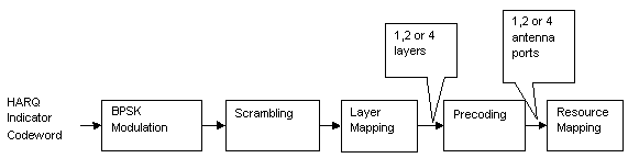
The HARQ Indicator codeword undergoes BPSK modulation, scrambling, layer mapping, precoding, and resource mapping as shown in this figure.
Modulation
The HARQ indicator codeword undergoes BPSK modulation resulting in a block of complex-valued modulated symbols, z(0), z(1), z(2).
Scrambling
The block of modulated symbols is bitwise multiplied with an orthogonal sequence and a cell-specific scrambling sequence to create a sequence of symbols, . The number of symbols, Msymb, is given by the equation . The PHICH spreading factor, , is 4 for a normal cyclic prefix and 2 for an extended cyclic prefix.
The orthogonal sequence allows multiple PHICHs to be mapped to the same set of resource elements.
Scrambling with a cell-specific sequence serves the purpose of intercell interference rejection. When a UE descrambles a received bitstream with a known cell specific scrambling sequence, interference from other cells will be descrambled incorrectly and therefore only appear as uncorrelated noise.
The complex scrambled symbols, , are created according to this equation.
The first term, , is the orthogonal sequence symbol with index . The second term, , is the cell-specific scrambling sequence symbol. The third term, , is the modulated HARQ indicator symbol.
The three modulated symbols, z(0), z(1), z(2), are repeated times and scrambled to create a sequence of six or twelve symbols depending on whether a normal or extended cyclic prefix is used. When using a normal cyclic prefix, the first four scrambled symbols are created as shown in this figure.
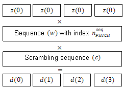
The variable w is an orthogonal scrambling sequence with index . The sequences are given in this table.
| Sequence Index | Orthogonal Sequence, | |
|---|---|---|
| Normal Cyclic Prefix, | Extended Cyclic Prefix, | |
| 0 | [+1 +1 +1 +1] | [+1 +1] |
| 1 | [+1 –1 +1 –1] | [+1 –1] |
| 2 | [+1 +1 –1 –1] | [+j +j] |
| 3 | [+1 –1 –1 +1] | [+j –j] |
| 4 | [+j +j +j +j] | — |
| 5 | [+j –j +j –j] | — |
| 6 | [+j +j –j –j] | — |
| 7 | [+j –j –j +j] | — |
The variable c is a cell-specific pseudo-random scrambling sequence created using a length-31 Gold sequence. The scrambling sequence is initialized using the slot number within the radio frame,ns, and the cell ID, .
Resource Group Alignment
As resource element groups (REGs) contain four resource elements (each able to contain one symbol) the blocks of scrambled symbols are aligned to create blocks of four symbols.
In the case of a normal cyclic prefix, each of the original complex modulated symbols, z(0), z(1), z(2), is represented by four scrambled symbols. Therefore, no alignment is required, as shown in this equation.
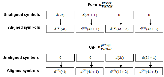
In the case of an extended cyclic prefix each of the original complex modulated symbols, z(0), z(1), z(2), is represented by two scrambled symbols. To create blocks of four symbols, zeros are added before or after blocks of two scrambled symbols depending on whether the PHICH index is odd or even. This allows two groups to be combined during the resource mapping stage and mapped to one REG. Groups of four symbols, d(0), are formed as shown in this figure.
Layer Mapping
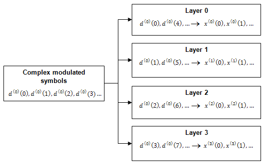
The complex symbols are mapped to one, two, or four layers depending on the number of transmit antennas used. The complex modulated input symbols, , are mapped onto v layers, .
If a single antenna port is used, only one layer is used. Therefore, .
If transmitter diversity is used, the input symbols are mapped to layers based on the number of layers.
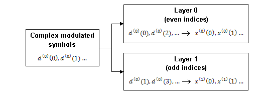
Two Layers — Even symbols are mapped to layer 0 and odd symbols are mapped to layer 1, as shown in this figure.
Four Layers — The input symbols are mapped to layers sequentially, as shown in the following figure.
Precoding
The precoder takes a block from the layer mapper, , and generates a sequence for each antenna port, . The variable p is the transmit antenna port number, and can assume values of {0}, {0,1}, or {0,1,2,3}.
For transmission over a single antenna port, no processing is carried out, as shown in this equation.
Precoding for transmit diversity is available on two or four antenna ports.
Two Antenna Port Precoding. An Alamouti scheme is used for precoding, which defines the relationship between input and output as shown in the following equation.
In the Alamouti scheme, two consecutive symbols, and , are transmitted in parallel using two antennas with the following mapping, where the asterisk symbol (*) denotes the complex conjugate operation.
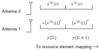
Since any two columns in the precoding matrix are orthogonal, the two symbols, and , can be separated at the UE.
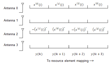
Four Antenna Port Precoding. Precoding for the four antenna port case depends on the index of the PHICH group, . If is even for a normal cyclic prefix or if is even for an extended cyclic prefix, the relationship between the input and output is defined by this equation.
In this scheme, two consecutive symbols are transmitted in parallel in two symbol periods using four antennas with this mapping, where the asterisk symbol (*) denotes the complex conjugate operation.
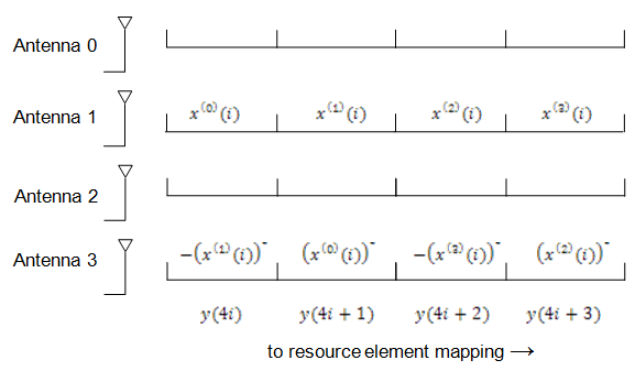
If is odd for a normal cyclic prefix or if is odd for an extended cyclic prefix, the relationship between the input and output is defined by this equation.
In this scheme, two consecutive symbols are transmitted in parallel in two symbol periods using four antennas with this mapping, where the asterisk symbol (*) denotes the complex conjugate operation.
Mapping to Resource Elements
PHICH Duration. The number of OFDM symbols used to carry the PHICH is configurable by the PHICH duration.
The PHICH duration is either normal or extended. A normal PHICH duration causes the PHICH to be present in only the first OFDM symbol. In general an extended PHICH duration causes the PHCH to be present in the first three OFDM symbols but there are some exceptions. The PHICH is present in the first two OFDM symbols under these exceptions.
Within subframe 1 and 6 when frame structure type 2 (TDD) is used
Within MBSFN subframes
Relationship between CFI and PHICH Duration. Since the control format indicator (CFI) configures how many OFDM symbols are used for mapping the physical downlink control channel (PDCCH) and hence which OFDM symbols are available for the physical downlink shared channel (PDSCH), care must be taken when using an extended PHICH duration so the PHICH is not mapped into the same region as the PDSCH.
For example, when using an extended PHICH in subframe zero of a frame structure type 1 (FDD) 10MHz subframe the first three OFDM symbols will contain PHICH. Therefore, the CFI must be set to 3 so the PDSCH is not mapped to OFDM symbols 0, 1, or 2, and so does not overlap with the PHICH.
Combining PHICH Sequences. Corresponding elements of each PHICH sequence are summed to create the sequence for each PHICH group, . The process is illustrated in this figure.
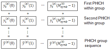
The variable is the n-th element within PHICH i on antenna port p.
PHICH Mapping Units. PHICHs are mapped to REGs using PHICH mapping units, , where is the index of the mapping unit. For a normal cyclic prefix, each PHICH group is mapped to a PHICH mapping unit. In the case of an extended cyclic prefix, two PHICH groups are mapped to one PHICH mapping unit. Due to the location of the padding zeros added during resource group alignment, when two consecutive groups are added, the zeros of one group overlap the data of the other.
Mapping to REGs. Each mapping unit contains twelve symbols. To map these twelve symbols to REGs, the mapping units are split into three groups of four symbols (quadruplets).
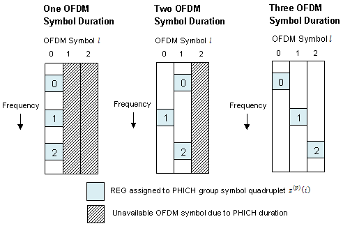
Each of the three symbol quadruplets, , is mapped to a REG, , so the PHICH is spread over all available OFDM symbols and resource blocks.
The OFDM symbol index, , is set so adjacent quadruplets are spread amongst the available OFDM symbols, as illustrated in this figure.
The subcarrier index, , of the REG is based upon the cell ID, , and is chosen to spread the three symbol quadruplets over the entire bandwidth.
See Also
ltePHICH | ltePHICHInfo | ltePHICHIndices | ltePHICHPRBS | lteDLResourceGrid | lteLayerMap | lteLayerDemap | lteDLPrecode | lteDLDeprecode | lteCRCEncode | lteCRCDecode | lteSymbolModulate | lteSymbolDemodulate