Phase Noise Analysis in VCO
This example shows how to measure and analyze the effect of phase noise in a voltage controlled oscillator (VCO). Using a Ring Oscillator VCO block and VCO testbench from Mixed-Signal Blockset, this example defines the typical phase noise levels from datasheet specifications and validates the VCO.
Set Up VCO Testbench Model
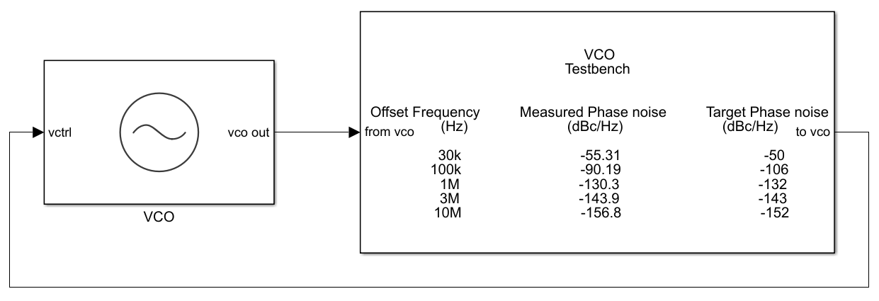
Open the model vcoPhaseNoiseAnalysis. The model consists of a Ring Oscillator VCO block and a VCO Testbench.
open_system('vcoPhaseNoiseAnalysis.slx')

VCO Specifications and Phase Noise Impairments
Double click the VCO block to open the Block Parameters dialog box. In the Configuration tab, the Voltage Sensitivity (Hz/V) is set to 125e6. In the Impairment tab, check that the Add phase noise option is enabled. Phase noise frequency offset (Hz) and Phase noise level (dBc/Hz) parameters represent a typical phase noise profile in a VCO. Once the phase noise data has been entered press the button named Estimate phase noise parameters which will automatically compute Period jitter and Flicker corner frequency parameters. To learn more about phase noise parameters in VCO, see Phase Noise in Oscillators.
To assess the quality of these parameters, press Plot fit button at the very bottom which will open up a figure window comparing the actual and estimated phase noise profile as shown below:

To observe the effects of the phase noise parameters change the Period jitter value to 1.2e-15 and proceed to configure VCO Testbench block.
Modify VCO Testbench According to VCO Specifications
Double click the VCO Testbench block to open the Block Parameters dialog box. In the Stimulus tab, Control voltage (V) is set to 4. Next, in Setup tab Resolution bandwidth (Hz) is set to 15e3 i.e. 15KHz considering the lowest frequency offset point for which phase noise value needs to be computed is 30KHz. Also, No. of spectral averages is set to 4. For this simulation Hold-off time (s) will be set to 0.
Alternatively, one can use Autofill setup parameters button to confugure the testbench for phase noise measurement. Also, check that in the Target Metric tab, the Phase noise frequency offset (Hz) and Phase noise level (dBc/Hz) parameters match the values set in the VCO block.
Plot Phase Noise Profile
Run the simulation for 0.4 ms, according to the Recommmended min. simulation stop time (s) in the Block Parameters dialog box of VCO Testbench.
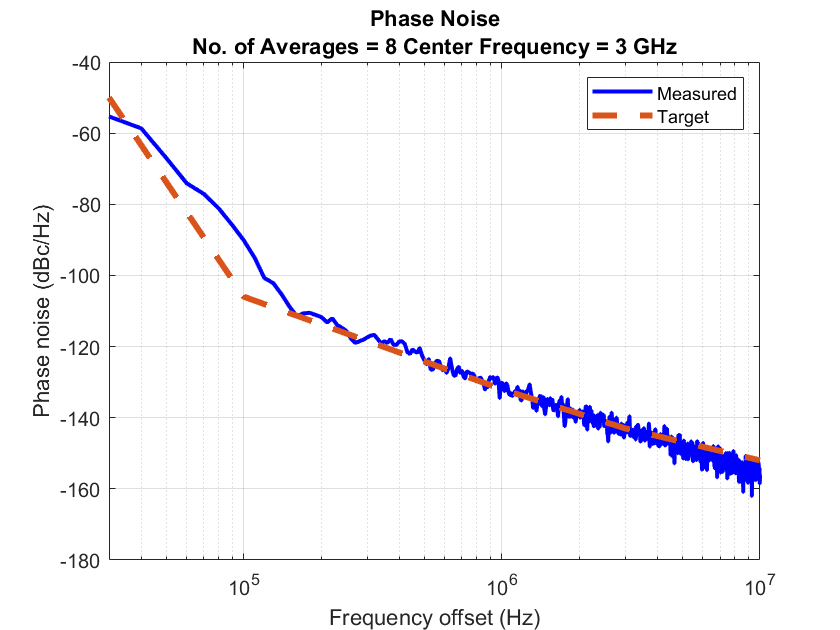
Once the simulation is complete, the phase noise profile is displayed on the icon of the VCO Testbench. The measured phase noise is comparable to target phase noise.
In the Block Parameters dialog box of VCO, click the Plot measurement button to plot the phase noise profile of the VCO. Notice that the VCO operating frequency is 3 GHz, and that the measured and targeted phase noise profiles match.