phased.ADPCACanceller
Adaptive DPCA (ADPCA) pulse canceller
Description
The phased.ADPCACanceller System object™ implements an adaptive displaced phase center array (ADPCA) pulse canceller for a uniform linear array (ULA).
To compute the output signal of the space time pulse canceller:
Create the
phased.ADPCACancellerobject and set its properties.Call the object with arguments, as if it were a function.
To learn more about how System objects work, see What Are System Objects?
Creation
Description
adpcaCancel = phased.ADPCACanceller
adpcaCancel = phased.ADPCACanceller(Name=Value)Name set to the specified
Value. Specify optional pairs of arguments as
(Name1=Value1,...,NameN=ValueN)
where Name is the argument name and Value is the
corresponding value. Name-value arguments must appear after other arguments, but the order
of the pairs does not matter.
Properties
Usage
Syntax
Description
Y = adpcaCancel(X,cutidx)X.
The algorithm calculates the processing weights according to the range cell specified by
cutidx. The output Y contains the result of
pulse cancellation either before or after Doppler filtering, depending on the
PreDopplerOutput property value.
This syntax is applicable when you set the DirectionSource
property to 'Property' and the DopplerSource
property to 'Property'.
Input Arguments
Output Arguments
Object Functions
To use an object function, specify the
System object as the first input argument. For
example, to release system resources of a System object named obj, use
this syntax:
release(obj)
Examples
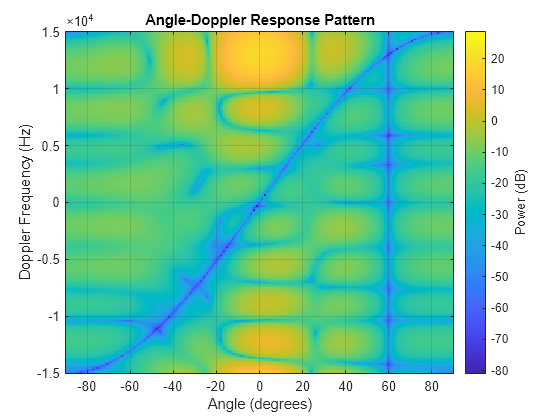
Process a radar data cube using an ADPCA processor. Weights are calculated for the 71st cell of the data cube. Set the look direction to (0,0) degrees and the Doppler shift to 12.980 kHz.
Load radar data file and compute weights
load STAPExampleData;
canceller = phased.ADPCACanceller('SensorArray',STAPEx_HArray,...
    'PRF',STAPEx_PRF,...
    'PropagationSpeed',STAPEx_PropagationSpeed,...
    'OperatingFrequency',STAPEx_OperatingFrequency,...
    'NumTrainingCells',100,...
    'WeightsOutputPort',true,...
    'DirectionSource','Input port',...
    'DopplerSource','Input port');
[y,w] = canceller(STAPEx_ReceivePulse,71,[0; 0],12.980e3);
Create AnglerDoppler System object and plot response
sAngeDop = phased.AngleDopplerResponse(...
    'SensorArray',canceller.SensorArray,...
    'OperatingFrequency',canceller.OperatingFrequency,...
    'PRF',canceller.PRF,...
    'PropagationSpeed',canceller.PropagationSpeed);
plotResponse(sAngeDop,w)
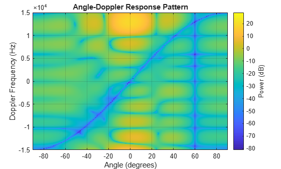
Process a radar data cube using an ADPCA processor. Weights are calculated for the 71st cell of the data cube. Load the data cube from STAPExampleData.mat. Quantize the weights to 4 bits. Set the look direction to (0,0) degrees and the Doppler shift to 12.980 kHz.
load STAPExampleData;
sADPCA = phased.ADPCACanceller('SensorArray',STAPEx_HArray,...
    'PRF',STAPEx_PRF,...
    'PropagationSpeed',STAPEx_PropagationSpeed,...
    'OperatingFrequency',STAPEx_OperatingFrequency,...
    'NumTrainingCells',100,...
    'WeightsOutputPort',true,...
    'DirectionSource','Input port',...
    'DopplerSource','Input port',...
    'NumPhaseShifterBits',4);
[y,w] = sADPCA(STAPEx_ReceivePulse,71,[0; 0],12.980e3);
sAngDop = phased.AngleDopplerResponse(...
    'SensorArray',sADPCA.SensorArray,...
    'OperatingFrequency',sADPCA.OperatingFrequency,...
    'PRF',sADPCA.PRF,...
    'PropagationSpeed',sADPCA.PropagationSpeed);
plotResponse(sAngDop,w);
Algorithms
References
[1] Guerci, J. R. Space-Time Adaptive Processing for Radar. Boston: Artech House, 2003.
[2] Ward, J. “Space-Time Adaptive Processing for Airborne Radar Data Systems,” Technical Report 1015, MIT Lincoln Laboratory, December, 1994.
Extended Capabilities
Version History
Introduced in R2011a