clutterSurfaceRCS
Surface clutter radar cross section
Syntax
Description
Examples
Calculate the radar cross section of a clutter patch and estimate the clutter-to-noise ratio at the receiver. Assume that the patch is 1000 meters away from the radar system and the azimuth and elevation beamwidths are 1 degree and 3 degrees, respectively. Also assume that the grazing angle is 20 degrees, the pulse width is 10 microseconds, and the radar is operated at a wavelength of 1 cm with a peak power of 5 kw.
rng    = 1000;
bwAz   = 1;
bwEl   = 3;
graz   = 20;
tau    = 10e-6;
lambda = 0.01;
ppow   = 5000;
Calculate the NRCS.
nrcs = landreflectivity('Mountains',graz)nrcs = 0.1082
Calculate clutter RCS using the calculated NRCS.
rcs = clutterSurfaceRCS(nrcs,rng,bwAz,bwEl,graz,tau)
rcs =
288.9855
Calculate clutter-to-noise ratio using the calculated RCS.
cnr = radareqsnr(lambda,rng,ppow,tau,'rcs',rcs)cnr = 62.5974
Since R2025a
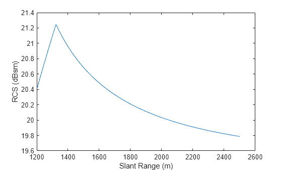
This example shows the RCS of the illuminated clutter region calculated as a function of slant range.
First, calculate the corresponding grazing angles for a set of ranges between 1.1 and 3 km. The radar is located at an altitude of 1 km and operates at a frequency of 1 GHz. It has a 5 degree symmetric beamwidth and a pulse width corresponding to 100 meters.
alt = 1e3;
freq = 1e9;
beamwidth = 5;
tau = 2*100/physconst('lightspeed');
slantRange = linspace(1.2e3,2.5e3,1e3).';
graze = asind(alt./slantRange);
Next, calculate surface NRCS using the Barton constant-gamma reflectivity model for farmland.
nrcs = landreflectivity('Farm',graze,freq);Finally, calculate RCS and plot in dBsm. The inflection point around 1.3 km is caused by switching from the beam-limited clutter calculation to the pulse-limited clutter calculation.
rcs = clutterSurfaceRCS(nrcs,slantRange,beamwidth,beamwidth,graze,tau);
plot(slantRange,10*log10(rcs))
xlabel('Slant Range (m)')
ylabel('RCS (dBsm)')
Input Arguments
Output Arguments
More About
References
[1] Barton, David K. Radar Equations for Modern Radar. Norwood, MA: Artech House, 2013.
[2] Long, Maurice W. Radar Reflectivity of Land and Sea. Boston: Artech House, 2001.
[3] Nathanson, Fred E., J. Patrick Reilly, and Marvin N. Cohen. Radar Design Principles. Mendham, NJ: SciTech Publishing, 1999.
Extended Capabilities
Version History
Introduced in R2021a
See Also
landreflectivity | seareflectivity | radareqsnr | surfacegamma | grazingang