ROS Read Scan, ROS 2 Read Scan
Libraries:
ROS Toolbox /
ROS
ROS Toolbox /
ROS 2
Description
The Read Scan block extracts range, scan and intensity data from a ROS or ROS 2 laser scan message. You can select the message parameters of a topic active on a live ROS or ROS 2 network, or specify the message parameters separately. The input messages are specified as a nonvirtual bus. Use the ROS Subscribe or the ROS 2 Subscribe block to receive a message from the network and input the message to the Read Scan block. For ROS and ROS 2 models, you must use the blocks in the respective ROS and ROS 2 library.
Examples
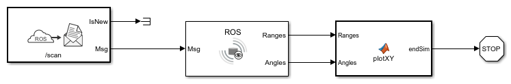
Read a ROS Scan Message in Simulink
Read in a laser scan message from a ROS network and calculate the Cartesian coordinate points to visualize with a 2D plot.
Ports
Input
Output
Parameters
Extended Capabilities
Version History
Introduced in R2022a
See Also
rosReadScanAngles | rosReadCartesian | rosReadLidarScan | rosPlot