Generate Standalone ROS 2 Node from MATLAB Function
This example explains how to remotely deploy a standalone ROS 2 node from a Windows® computer to a remote Linux® machine. The process starts with generating C++ code in MATLAB® for a proportional controller. Next, the code is built and executed as a ROS 2 node on the remote device. The deployed node is then used to control a differential-drive robot equipped with ROS 2 capabilities.
Introduction
This example shows how to:
Configure MATLAB to connect to a ROS-enabled robot simulator using ROS 2.
Generate C++ code for MATLAB function in Windows host machine.
Deploy standalone ROS 2 node on Linux remote machine.
Prerequisites
To run this example, you are required to set up Windows Subsystem for Linux (WSL) in your host machine and create a Docker image for Gazebo. For more information on how to configure Docker, see Install and Set Up Docker for ROS, ROS 2, and Gazebo.
Start Docker Container
With the prerequisites set up and Docker image created, the first step is to start a Docker container.
To start the Docker container, open a terminal in WSL and enter this command:
$ docker run -it --net=host -v /dev/shm:/dev/shm --name ros2_standalone_node <image-name>
Here, 'ros2_standalone_node' is the Docker container name. Replace the <image-name> with the name of the Docker image you created in the prerequisite section.
Get IP Address of Docker Container
While the Docker container is running, obtain the IP address of the Docker container running on the remote device. This IP address is necessary for establishing an SSH connection and accessing the Gazebo simulator. Note that the IP address of the Docker container is the same as the IP of WSL.
To retrieve this IP address, run the following command in the WSL terminal:
$ ifconfig
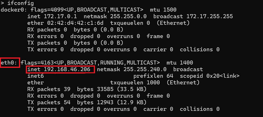
The connection type can vary depending on how your host is connected to the Docker container. In this case use the Ethernet (eth0), however, in many cases the wireless (wlan0) is the appropriate connection.
Start Gazebo Robot Simulator in Docker Container
Once the container is running, start the Gazebo robot simulator inside the Docker container.
Open a terminal within the Docker container by executing the following command in the WSL terminal:
$ docker exec -it ros2_standalone_node /bin/bash
Here, ros2_node_deployment is the name of the Docker container.
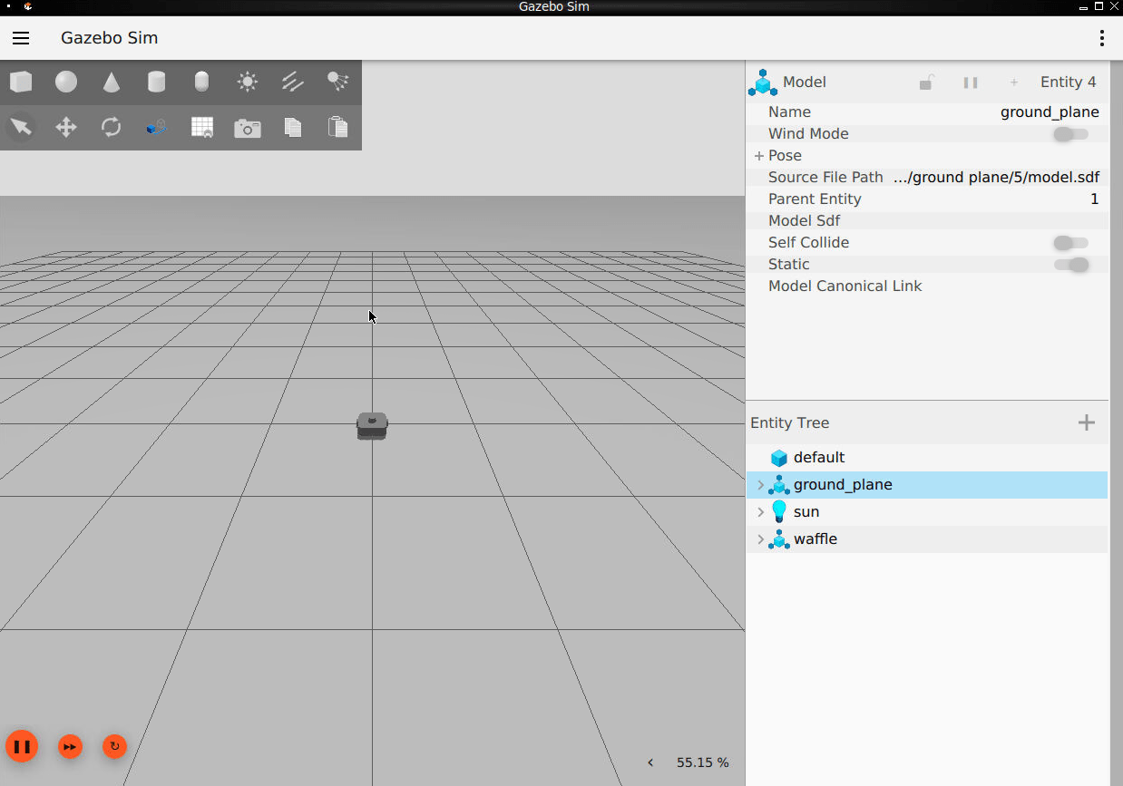
In the Docker container terminal, launch the TurtleBot in a Gazebo world by running the following command:
$ source start-gazebo-empty-world.sh
To view the Gazebo world, open a web browser on your Windows or WSL machine and connect to the URL <docker-ip-address>:8080. If WSL is running on the same host machine, you can simply use localhost:8080. You can now visualize and interact with the Gazebo world directly in your web browser.
Configure MATLAB for ROS 2 Network
Launch MATLAB on your host machine and set the ROS_DOMAIN_ID environment variable to 25 to match the robot simulator's ROS settings.
Once the domain ID is set, run the following command in MATLAB to verify that the topics from the robot simulator are visible:
setenv('ROS_DOMAIN_ID','25')
ros2 topic list
Control ROS 2 Enabled Robot from MATLAB
With the Gazebo simulator running, you can now control the ROS 2-enabled robot directly from MATLAB. This example uses the robotROS2FeedbackControl function, which is a proportional controller designed to guide the robot to a desired position.
Understand robotROS2FeedbackControl function
It subscribes to the /odom topic to retrieve the robot's current odometry data.
It publishes control commands as
geometry_msgs/Twistmessages to the /cmd_vel topic, directing the robot to move toward the desired position using proportional control.
Run Proportional Controller
Open MATLAB and run the robotROS2FeedbackControl function to control the robot.
robotROS2FeedbackControl
By default, the robot moves toward the destination defined by the defaultDesiredPos variable. You can also modify this variable to set a different target position.
As the robot moves, observe its trajectory in the generated plot. Keep this figure open for later comparison between MATLAB execution and the behavior of the generated executable node
Dynamically Update Destination
Open a new terminal inside the Docker container by running this command.
~$ docker exec -it ros2_standalone_node /bin/bash
Inside the container terminal, source the ROS repository, set the ROS_DOMAIN_ID to 25, and publish new destination coordinates by sending a std_msgs/Float64MultiArray message to the /dest topic. Use the following command to send a std_msgs/Float64MultiArray message to the /dest topic.
~$ source /opt/ros/jazzy/local_setup.bash
~$ export ROS_DOMAIN_ID=25
~$ ros2 topic pub -1 /dest std_msgs/Float64MultiArray "{data:[0,0]}"
Adjust Controller Parameters
You can also adjust the distanceThre, linearVelocity, and rotationGain values in the robotROS2FeedbackControl.m to change the desired robot behavior. For the proportional controller in this example, you must specify values in these ranges to ensure robust performance. Alternatively, you can replace the proportional controller with a custom controller for performance comparison. To view the behavior, reset the robot on the Docker container by relaunching Gazebo.
distanceThre: 0<x<1
linearVelocity: 0<x<3
rotationGain: 0<x<6
Terminate Controller
The controller loop automatically terminates when either of the following conditions is met:
The robot reaches the goal position.
More than 40 seconds have elapsed since the controller started.
Alternatively, to terminate the controller manually at any time, you can opt of any of these methods:
Use Ctrl-C in the MATLAB command window to stop the controller.
In the Docker container terminal, use the following command to send a stop signal to the
/stoptopic:
~$ ros2 topic pub -1 /stop std_msgs/Bool "data: 1"
If you open a new terminal in the Docker container, remember to source the ROS repository and set the ROS_DOMAIN_ID to 25 before issuing commands.
Create Function for Code Generation
After testing the controller in MATLAB, modify the function to make it compatible for code generation.
Remove the lines of code related to plot.
Save the modified MATLAB function to
robotROS2FeedbackControlCodegen.m.Ensure any other modifications that you made in
robotROS2FeedbackControlfunction reflects inrobotROS2FeedbackControlCodegen.
Generate Executable for robotROS2FeedbackControlCodegen
To deploy executable on remote device, first ensure that remote device is up. To verify that, create a ros2device object. Specify the deviceAddress, username, and password values of the Docker container running Gazebo. This establishes an SSH connection between the remote device and MATLAB.
gazeboDockerDevice = ros2device('192.168.46.206',"user","password")
Before deploying executable, terminate all the running instance of Gazebo, use Ctrl+C in the Docker container terminal where Gazebo is running and then start a new instance.
Generate an executable node for the robotROS2FeedbackControlCodegen function. Specify the hardware as "Robot Operating System 2 (ROS 2)". Set the build action to "Build and run" so that the ROS 2 node starts running after you generate it. Specify the coder configuration parameters for remote deployment. This example specifies the remote device parameters of the Docker container. Set the following configuration parameters before remote deployment:
RemoteDeviceAddressis IP address of Docker container.RemoteDeviceUsernameis 'user'.RemoteDevicePasswordis 'password'.
Note that the actual values might be different for your remote device. Verify them before deployment.
cfg = coder.config("exe");
cfg.Hardware = coder.hardware("Robot Operating System 2 (ROS 2)");
cfg.Hardware.BuildAction = "Build and run";
cfg.Hardware.RemoteDeviceAddress = '192.168.46.206';
cfg.Hardware.RemoteDeviceUsername = "user";
cfg.Hardware.RemoteDevicePassword = "password";
cfg.Hardware.DeployTo = "Remote Device";
codegen robotROS2FeedbackControlCodegen -args {} -config cfg
Call plotPathFeedbackControl to plot the robot trajectory.
plotPathFeedbackControl
The cfg object generates and runs the ROS 2 node on your remote device. You can opt to deploy and run the ROS 2 node on the local machine by modifying the coder configuration object, cfg.
cfg = coder.config('exe');
cfg.Hardware = coder.hardware('Robot Operating System 2 (ROS 2)');
cfg.Hardware.BuildAction = 'Build and run';
cfg.Hardware.DeployTo = 'Localhost';
codegen robotROS2FeedbackControlCodegen -args {} -config cfg
plotPathFeedbackControl
Verify Generated ROS Node
After the generated executable starts running for the specified destination coordinates, verify the trajectory of the robot against the MATLAB execution. You can also observe the robot moving in Gazebo on the Docker container. You can publish a different destination coordinate while the robot is in motion. The Dynamically Update Destination section, which shows how to publish a new set of destination coordinates through a ROS 2 topic.
Terminate the generated ROS 2 node by using the stopNode function of the ros2Device object. Alternatively, you can terminate the execution by sending a message to the /stop topic.
stopNode(gazeboDockerDevice,'robotROS2FeedbackControlCodegen')At last, close Gazebo by using Ctrl-C on Docker container terminal where Gazebo is running.