Customize System Target Files
This section provides information on the structure of the system target file, guidelines for customizing a system target file, and a basic tutorial that helps you to produce a skeletal system target file.
Control Code Generation With the System Target File
The system target file controls the code generation stage of the build process. The system target file also lets you control the presentation of your target to the end user. The system target file provides
Definitions of variables that are fundamental to the build process, such as the value for the
CodeFormatTLC variableThe main entry point to the top-level TLC program that generates code
Target information for display in the System Target File Browser
A mechanism for defining target-specific code generation options (and other parameters related to the build process) and for displaying them in the Configuration Parameters dialog box
A mechanism for inheriting options from another target (such as the Embedded Real-Time (ERT) target)
Note that, although the system target file is a Target Language Compiler (TLC) file, it contains embedded MATLAB® code. Before creating or modifying a system target file, you should acquire a working knowledge of TLC and of the MATLAB language. Target Language Compiler and Scripts vs. Functions describe the features and syntax of both the TLC and MATLAB languages.
While reading this section, you may want to refer to the system target files provided
with the code generator. Most of these files are stored in the target-specific folders under
matlabroot/rtw/cmatlabroot/toolbox/rtw/targets
System Target File Naming and Location Conventions
A system target file must be located in a folder on the MATLAB path for the target to be displayed in the System Target File Browser and invoked in the build process. Follow the location and naming conventions for system target files and related target files given in Folder and File Naming Conventions.
System Target File Structure
Overview
This section is a guide to the structure and contents of a system target file. The following listing shows the general structure of a system target file. Note that this is not a complete code listing of a system target file. The listing consists of excerpts from each of the sections that make up a system target file.
%%----------------------------
%% Header Comments Section
%%----------------------------
%% SYSTLC: Example Real-Time Target
%%    TMF: my_target.tmf MAKE: make_rtw
%% Initial comments contain directives for STF Browser.
%% Documentation, date, copyright, and other info may follow.
          ...
%selectfile NULL_FILE
         ...
%%----------------------------
%% TLC Configuration Variables Section
%%----------------------------
%% Assign code format, language, target type.
%%
%assign CodeFormat = "Embedded-C"
%assign TargetType = "RT"
%assign Language   = "C"
%%
%%----------------------------
%% TLC Program Entry Point
%%----------------------------
%% Call entry point function.
%include "codegenentry.tlc"
%%
%%----------------------------
%% (OPTIONAL) Generate Files for Build Process
%%----------------------------
%include "mytarget_genfiles.tlc"
%%----------------------------
%% RTW_OPTIONS Section
%%----------------------------
/%
  BEGIN_RTW_OPTIONS
  %% Define rtwoptions structure array. This array defines target-specific
  %% code generation variables, and controls how they are displayed.
  rtwoptions(1).prompt = 'example code generation options';
        ...
  rtwoptions(6).prompt = 'Show eliminated blocks';
  rtwoptions(6).type = 'Checkbox';
         ...
  %----------------------------------------%
  % Configure RTW code generation settings %
  %----------------------------------------%
         ...
  %%----------------------------
  %% rtwgensettings Structure
  %%----------------------------
  %% Define suffix text for naming build folder here.
  rtwgensettings.BuildDirSuffix = '_mytarget_rtw'
  %% Callback compatibility declaration
  rtwgensettings.Version = '1';

  %% (OPTIONAL) target inheritance declaration
  rtwgensettings.DerivedFrom = 'ert.tlc';
  %% (OPTIONAL) other rtwGenSettings fields...
         ...
  END_RTW_OPTIONS
%/
%%----------------------------
%% targetComponentClass - MATHWORKS INTERNAL USE ONLY
%% REMOVE NEXT SECTION FROM USER_DEFINED CUSTOM TARGETS
%%----------------------------
/%
  BEGIN_CONFIGSET_TARGET_COMPONENT
  targetComponentClass = 'Simulink.ERTTargetCC';
  END_CONFIGSET_TARGET_COMPONENT
%/
If you are creating a custom target based on an existing system target file, you must
remove the targetComponentClass section (bounded by the directives
BEGIN_CONFIGSET_TARGET_COMPONENT and
END_CONFIGSET_TARGET_COMPONENT). This section is reserved for the use
of targets developed internally by MathWorks.
Header Comments
These lines at the head of the file are formatted as TLC comments. They provide required information to the System Target File Browser and to the build process. Note that you must place the browser comments at the head of the file, before other comments or TLC statements.
The presence of the comments enables the code generator to detect system target files. When the System Target File Browser is opened, the code generator scans the MATLAB path for TLC files that have formatted header comments. The comments contain the following directives:
SYSTLC: The descriptor that appears in the browser.
TMF: Name of the template makefile (TMF) to use during build process. When the target is selected, this filename is displayed in the Template makefile field of the Code Generation pane of the Configuration Parameters dialog box.
MAKE:
makecommand to use during build process. When the target is selected, this command is displayed in the Make command field of the Code Generation pane of the Configuration Parameters dialog box.
The following header comments are from
matlabroot/rtw/c/ert/ert.tlc
%% SYSTLC: Embedded Coder TMF: ert_default_tmf MAKE: make_rtw
%% SYSTLC: Create Visual C/C++ Solution File for Embedded Coder
.
.
.
Each comment can only contain a maximum of two lines.
If you do not specify the TMF field in the system target file, the
file is still valid. To change the value for theTemplateMakefile
parameter, you can instead use the callback function specified by
rtwgensettings.SelectCallback.
You can also use the callback function specified by
rtwgensettings.SelectCallback to change the value for external mode
parameters, ExtMode, ExtModeTransport,
ExtModeMexFile, or ExtModeIntrfLevel.
You can specify more than one group of directives in the header comments. Each such
group is displayed as a different target configuration in the System Target File Browser.
In the above example, the first two lines of code specify the default configuration of the
ERT target. The next two lines specify a configuration that creates and builds a
Microsoft®
Visual C++® Solution (.sln) file. The figure below shows how these
configurations appear in the System Target File Browser.

See Create a Custom Target Configuration for an example of customized header comments.
TLC Configuration Variables
This section of the system target file assigns global TLC variables that relate to the overall code generation process.
For an embedded target, in most cases you should simply use the global TLC variable
settings used by the ERT target (ert.tlc). It is especially important
that your system target file use the 'Embedded-C' value for the
CodeFormat TLC variable and uses the corresponding
rtwgensettings.DerivedFrom = 'ert.tlc' in the
RTW_OPTIONS section of the TLC file. Verify that values are assigned
to the following variables:
CodeFormat: TheCodeFormatTLC variable selects generated code features. The'Embedded-C'value for this variable is used by the ERT target. Your ERT-based target should specify'Embedded-C'as the value forCodeFormat. This selection is designed for production code, minimal memory usage, static memory allocation, and a simplified interface to generated code.For information on other values for the
CodeFormatTLC variable, see Compare System Target File Support Across Products.Language: The only valid value isC, which enables support forCorC++code generation as specified by the configuration parameterTargetLang.TargetType: The code generator defines the preprocessor symbolsRTandNRTto distinguish simulation code from real-time code. These symbols are used in conditional compilation. TheTargetTypevariable determines whetherRTorNRTis defined.Most targets are intended to generate real-time code. They assign
TargetTypeas follows.%assign TargetType = "RT"
Some targets, such as the model reference simulation target, accelerated simulation target, RSim target, and S-function target, generate code for use in nonreal time only. Such targets assign
TargetTypeas follows.%assign TargetType = "NRT"
TLC Program Entry Point and Related %includes
The code generation process normally begins with codegenentry.tlc.
The system target file invokes codegenentry.tlc as follows.
%include "codegenentry.tlc"
Note
codegenentry.tlc and the lower-level TLC files assume that
CodeFormat, TargetType, and
Language have been assigned. Set these variables before including
codegenentry.tlc.
If you need to implement target-specific code generation features, you should include
the TLC file mytarget_genfiles.tlc in your system target file. This
file provides a mechanism for executing custom TLC code before and after invoking
codegenentry.tlc. For information on this mechanism, see
Using mytarget_genfiles.tlc for an example of custom TLC code for execution after the main code generation entry point.
Target Development and the Build Process for general information on the build process, and for information on other build process customization hooks.
Another way to customize the code generation process is to call lower-level functions
(normally invoked by codegenentry.tlc) directly, and include your own
TLC functions at each stage of the process. This approach should be taken with caution.
See TLC Files for more information.
The lower-level functions called by codegenentry.tlc are
genmap.tlc: maps block names to corresponding language-specific block target files.commonsetup.tlc: sets up global variables.commonentry.tlc: starts the process of generating code.
RTW_OPTIONS Section
The RTW_OPTIONS section is bounded by the directives:
/%
  BEGIN_RTW_OPTIONS
.
.
.
  END_RTW_OPTIONS
%/
The first part of the RTW_OPTIONS section defines an array of
rtwoptions structures. This structure is discussed in Using rtwoptions to Display Custom Target Options.
The second part of the RTW_OPTIONS section defines
rtwgensettings, a structure defining the build folder name and other
settings for the code generation process. See rtwgensettings Structure for information about
rtwgensettings.
rtwgensettings Structure
The final part of the system target file defines the rtwgensettings structure. This structure stores information that
is written to the model.rtwrtwgensettings fields of most interest to target
developers are
rtwgensettings.Version: Use this property to enablertwoptionscallbacks and to use the Callback API inrtwgensettings.SelectCallback.Note
To use callbacks, you must set
rtwgensettings.Versionto a non-empty value. For example:rtwgensettings.Version = '1';
Add the statement above to the Configure RTW code generation settings section of the system target file.
rtwgensettings.DerivedFrom: This structure field defines the system target file from which options are to be inherited. See Inheriting Target Options.rtwgensettings.SelectCallback: This structure field specifies aSelectCallbackfunction. You must setrtwgensettings.Versionto a non-empty value or your callback will be ignored.SelectCallbackis associated with the target rather than with any of its individual options. TheSelectCallbackfunction is triggered when you select a target by setting the System target file configuration parameter.The
SelectCallbackfunction is useful for setting up (or disabling) configuration parameters specific to the target.The following code installs a
SelectCallbackfunction:rtwgensettings.SelectCallback = 'my_select_callback_handler(hDlg,hSrc)';
The arguments to the
SelectCallbackfunction(hDlg, hSrc)are handles to private data used by the callback API functions.Note
If you have developed a custom target and you want it to be compatible with model referencing, you must implement a
SelectCallbackfunction to declare model reference compatibility. See Support Model Referencing.rtwgensettings.ActivateCallback: this property specifies anActivateCallbackfunction. TheActivateCallbackfunction is triggered when the active configuration set of the model changes. This could happen during model loading, and also when the user changes the active configuration set.The following code installs an
ActivateCallbackfunction:rtwgensettings.ActivateCallback = 'my_activate_callback_handler(hDlg,hSrc)';
The arguments to the
ActivateCallbackfunction(hDlg,hSrc)are handles to private data used by the callback API functions.rtwgensettings.PostApplyCallback: this property specifies aPostApplyCallbackfunction. ThePostApplyCallbackfunction is triggered when the user clicks the Apply or OK button after editing options in the Configuration Parameters dialog box. ThePostApplyCallbackfunction is called after the changes have been applied to the configuration set.The following code installs an
PostApplyCallbackfunction:rtwgensettings.PostApplyCallback = 'my_postapply_callback_handler(hDlg,hSrc)';
The arguments to the
PostApplyCallbackfunction(hDlg, hSrc)are handles to private data used by the callback API functions.rtwgensettings.BuildDirSuffix: To identify the build folder created by the build process, most system target files define a folder name suffix. To form the name of the build folder, the build process appends the suffix defined in thertwgensettings.BuildDirSuffixfield to the model name. You can modify the suffix by specifying a new string value forrtwgensettings.BuildDirSuffix. For example:rtwgensettings.BuildDirSuffix = '_mytarget_rtw'
The build process creates a build folder named
model_mytarget_rtwDo not use a function to specify the new string value. For example:
rtwgensettings.BuildDirSuffix = my_get_build_suffix(bdroot);
Additional Code Generation Options
Configure Generated Code with TLC describes additional TLC code generation variables. End users of a target can assign these variables by entering a MATLAB command of the form
set_param(modelName,'TLCOptions','-aVariable=val');
However, the preferred approach is to assign these variables in the system target file using statements of the form:
%assign Variable = val
For readability, we recommend that you add such assignments in the section of the system target file after the comment Configure RTW code generation settings.
Model Reference Considerations
See Support Model Referencing for important information on system target file and other modifications you may need to make to support the code generator model referencing features.
Define and Display Custom Target Options
Using rtwoptions to Display Custom Target Options
You control the options to display in the Code Generation pane in
the Configuration Parameters dialog box by customizing the rtwoptions
structure in your system target file.
The fields of the rtwoptions structure define variables and
associated user interface elements to be displayed in the Configuration Parameters dialog
box. Using the rtwoptions structure array, you can define
target-specific options displayed in the dialog box and organize options into categories.
You can also write callback functions to specify how these options are processed.
When the Code Generation pane opens, the
rtwoptions structure array is scanned and the listed options are
displayed. Each option is represented by an assigned user interface element (check box,
edit field, menu, or push button), which displays the current option value.
The user interface elements can be in an enabled or disabled (appears dimmed) state. If an option is enabled, the user can change the option value. If an option is disabled, the option uses the default value and the user cannot change the option value.
You can also use the rtwoptions structure array to define special
NonUI elements that cause callback functions to be executed, but that are not displayed in
the Code Generation pane. See NonUI Elements.
The elements of the rtwoptions structure array are organized into
groups. Each group of items begins with a header element of type
Category. The default field of a Category header
must contain a count of the remaining elements in the category.
The Category header is followed by options to be displayed on the
Code Generation pane. The header in each category is followed by
one or more option definition elements.
Each category of target options corresponds to options listed under Code Generation in the Configuration Parameters dialog box.
The table rtwoptions Structure Fields Summary summarizes the fields of the
rtwoptions structure.
Example rtwoptions Structure. The following code defines an rtwoptions structure array. The
default field of the first (header) element is set to 4, indicating
the number of elements that follow the header.
  rtwoptions(1).prompt        = 'userPreferred target options (I)';
  rtwoptions(1).type          = 'Category';
  rtwoptions(1).enable        = 'on';
  rtwoptions(1).default       = 4;   % number of items under this category
                                     % excluding this one.
  rtwoptions(1).popupstrings  = '';  % At the first item, user has to
  rtwoptions(1).tlcvariable   = '';  % initialize all supported fields
  rtwoptions(1).tooltip       = '';
  rtwoptions(1).callback      = '';
  rtwoptions(1).makevariable  = '';

  rtwoptions(2).prompt        = 'Execution Mode';
  rtwoptions(2).type          = 'Popup';
  rtwoptions(2).default       = 'Real-Time';
  rtwoptions(2).popupstrings  = 'Real-Time|UserDefined';
  rtwoptions(2).tlcvariable   = 'tlcvariable1';
  rtwoptions(2).tooltip       = ['See this text as tooltip'];

  rtwoptions(3).prompt        = 'Log Execution Time';
  rtwoptions(3).type          = 'Checkbox';
  rtwoptions(3).default       = 'on';
  rtwoptions(3).tlcvariable   = 'RL32LogTETModifier';
  rtwoptions(3).tooltip       = ['']; % no tooltip

  rtwoptions(4).prompt        = 'Real-Time Interrupt Source';
  rtwoptions(4).type          = 'Popup';
  rtwoptions(4).default       = 'Timer';
  rtwoptions(4).popupstrings  = 'Timer|5|6|7|8|9|10|11|12|13|14|15';
  rtwoptions(4).tlcvariable   = 'tlcvariable3';
  rtwoptions(4).callback      = 'usertargetcallback(hDlg, hSrc, ''tlcvariable3'')';
  rtwoptions(4).tooltip       = [''];
  rtwoptions(4).tooltip       = ['See TLC file for how to use reserved '...
    ' keyword ''hDlg'', and ''hSrc''.'];
...
  rtwoptions(5).prompt        = 'Signal Logging Buffer Size in Doubles';
  rtwoptions(5).type          = 'Edit';
  rtwoptions(5).default       = '100000';
  rtwoptions(5).tlcvariable   = 'tlcvariable2';
  rtwoptions(5).tooltip       = [''];
The first element adds a userPreferred target options (I) pane
under Code Generation in the Configuration Parameters dialog box.
The pane displays the options defined in rtwoptions(2),
rtwoptions(3), rtwoptions(4), and
rtwoptions(5).
If you want to define a large number of options, you can define multiple
Category groups within a single system target file.
Note the rtwoptions structure and callbacks are written in
MATLAB code, although they are embedded in a TLC file. To verify the syntax of
your rtwoptions structure definitions and code, you can execute the
commands at the MATLAB prompt by copying and pasting them to the MATLAB Command Window.
To learn more about usertarget.tlc and the example callback files
provided with it, see Example System Target File With Customized rtwoptions.
For more examples of target-specific rtwoptions definitions, see the
target.tlcmatlabroot/rtw/c
rtwoptions Structure Fields Summary lists the fields of the rtwoptions structure.
rtwoptions Structure Fields Summary
| Field Name | Description |
|---|---|
| For examples of callback usage, see Example System Target File With Customized rtwoptions. |
| Do not use
For examples of callback usage, see Example System Target File With Customized rtwoptions. |
| Default value of the option (empty if the |
| Must be |
| Template makefile token (if any)
associated with the option. The |
modelReferenceParameterCheck | Specifies whether the option must have the same value in a referenced
model and its parent model. If this field is unspecified or has the value
'on' the option values must be same. If the field is
specified and has the value 'off' the option values can
differ. See Controlling Configuration Option Value Agreement. |
| Element that is not displayed, but is used to invoke a close or open callback. See NonUI Elements. |
| Do not use For examples of callback usage, see Example System Target File With Customized rtwoptions. |
| If 'rt_|_rt|none' |
| Label for the option. |
| Name of TLC variable associated with the option. |
| Help text displayed when mouse is over the item. |
| Type of element: |
NonUI Elements. Elements of the rtwoptions array that have type
NonUI exist solely to invoke callbacks. A NonUI
element is not displayed in the Configuration Parameters dialog box. You can use a
NonUI element if you want to execute a callback that is not
associated with a user interface element, when the dialog box opens or closes. See the
next section, Example System Target File With Customized rtwoptions for an
example.
Note
The default value of an element of type NonUI or
Edit determines the set of values allowed for that element.
If the default value is
'0'or'1':For type
NonUI, the element stores a Boolean value.For type
Edit, the element stores a value of typeint32.
If the default value contains an integer other than
'0'or'1', the element stores a value of typeint32.If the default value does not contain an integer, the element is evaluated as a character vector.
Example System Target File With Customized rtwoptions
A working system target file, with MATLAB® file callback functions, has been provided as an example of how to use the rtwoptions structure to display and process custom options on the Code Generation pane. The examples are compatible with the callback API.
The example target files include:
usertarget.tlc: The example system target file. This file illustrates how to define custom menus, check boxes, and edit fields. The file also illustrates the use of callbacks.usertargetcallback.m: A MATLAB® file callback invoked by a menu.
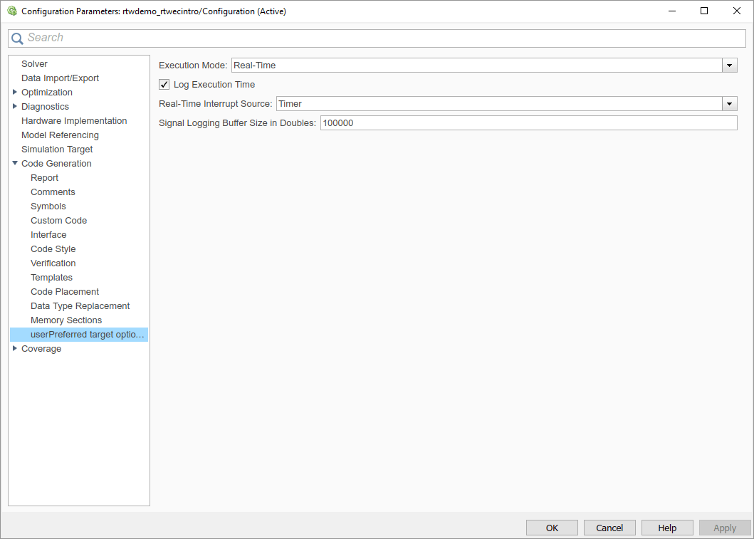
Refer to the example files while reading this section. The example system target file, usertarget.tlc, illustrates the use of rtwoptions to display the following custom target options:
The Execution Mode menu.
The Log Execution Time check box.
The Real-Time Interrupt Source menu. The menu executes a callback defined in an external file,
usertargetcallback.m. The TLC variable associated with the menu is passed in to the callback, which displays the menu's current value.The edit field Signal Logging Buffer Size in Doubles.
Study the example code while interacting with the example target options in the Configuration Parameters dialog box. To interact with the example target file,
Open a model of your choice.
Open the Configuration Parameters dialog box and select the Code Generation pane.
Click Browse. The System Target File Browser opens. Select
usertarget.tlc. Then click OK.Observe that the Code Generation pane contains a custom sub-tab: userPreferred target options (I).
As you interact with the options in this category and open and close the Configuration Parameters dialog box, observe the messages displayed in the MATLAB Command Window. These messages are printed from code in the system target file, or from callbacks invoked from the system target file.
Inheriting Target Options
ert.tlc provides a basic set of Embedded Coder® code generation options. If your target is based on
ert.tlc, your system target file should normally inherit the options
defined in ERT.
Use the rtwgensettings.DerivedFrom field in the
rtwgensettings structure to define the system target file from which
options are to be inherited. You should convert your custom target to use this mechanism
as follows.
Set the rtwgensettings.DerivedFrom field value as in
the following example:
rtwgensettings.DerivedFrom = 'stf.tlc';
where stf is the name of the system target file from which options
are to be inherited. For example:
rtwgensettings.DerivedFrom = 'ert.tlc';
When the Configuration Parameters dialog box executes this line of code, it includes
the options from stf.tlc automatically. If stf.tlc
is a MathWorks internal system target file that has been converted to a new layout, the
dialog box displays the inherited options using the new layout.
Handling Unsupported Options. If your target does not support all of the options
inherited from ert.tlc, you should detect unsupported option settings
and display a warning or error message. In some cases, if a user has selected an option
your target does not support, you may need to abort the build process. For example, if
your target does not support the Generate an example main
program option, the build process should not be allowed to proceed if that
option is selected.
Even though your target may not support all inherited
ERT options, it is required that the ERT options are retained in the Code
Generation pane of the Configuration Parameters dialog box. Do not simply
remove unsupported options from the rtwoptions structure in the
system target file. Options must be in the dialog box to be scanned by the code
generator when it performs optimizations.
For example, you may want to prevent users from turning off the Single output/update function option. It may seem reasonable to
remove this option from the dialog box and simply assign the TLC variable
CombineOutputUpdateFcns to on. However, if the
option is not included in the dialog box, the code generator assumes that output and
update functions are not to be combined. Less efficient code is
generated as a result.
Tips and Techniques for Customizing Your System Target File
Introduction
The following sections include information on techniques for customizing your system target file, including:
How to invoke custom TLC code from your system target file
Approaches to supporting multiple development environments
Considerations for when you update your system target file
Required and Recommended %includes
If you need to implement target-specific code generation features, we recommend that
your system target file include the TLC file
mytarget_genfiles.tlc.
Once your system target file has set up the required TLC environment, you must include
codegenentry.tlc to start the standard code generation
process.
mytarget_genfiles.tlc provides a mechanism for executing custom TLC
code after the main code generation entry point. See Using mytarget_genfiles.tlc.
Using mytarget_genfiles.tlc. mytarget_genfiles.tlc (optional) is useful as a central file from
which to invoke target-specific TLC files that generate additional files as part of your
target build process. For example, your target may create sub-makefiles or project files
for a development environment, or command scripts for a debugger to do automatic
downloads.
The build process can then invoke these generated files either directly from the
make process or after the executable is created. This is done with the
STF_make_rtw_hook.m
The following TLC code shows an example mytarget_genfiles.tlc
file.
%selectfile NULL_FILE

%assign ModelName = CompiledModel.Name

%% Create Debugger script
%assign model_script_file = "%<ModelName>.cfg"
%assign script_file = "debugger_script_template.tlc"

%if RTWVerbose
   %selectfile STDOUT
   ### Creating %<model_script_file>
   %selectfile NULL_FILE
%endif

%include "%<script_file>"
%openfile bld_file = "%<model_script_file>"
%<CreateDebuggerScript()>
%closefile bld_file
Handling Aliases for Target Option Values
This section describes utility functions that can be used to detect and resolve alias
values or legacy values when testing user-specified values for the target device type
(ProdHWDeviceType) and the code replacement library
(CodeReplacementLibrary).
RTW.isHWDeviceTypeEq. To test if two target device type values represent the same hardware device, invoke the following function:
result = RTW.isHWDeviceTypeEq(type1,type2)
where type1type2
The RTW.isHWDeviceTypeEq function returns true if
type1type2
RTW.isHWDeviceTypeEq('Specified','Generic->Custom')For a description of the target device type option
ProdHWDeviceType, see the command-line information for the
Hardware Implementation pane parameters Device vendor and Device type.
RTW.resolveHWDeviceType. To return the device type value for a hardware device, given a value that might be an alias or legacy value, invoke the following function:
result = RTW.resolveHWDeviceType(type)
where type
The RTW.resolveHWDeviceType function returns the device type
value of the device. For example, the following calls both return
'Generic->Custom':
RTW.resolveHWDeviceType('Specified')
RTW.resolveHWDeviceType('Generic->Custom')
For a description of the target device type option
ProdHWDeviceType, see the command-line information for the
Hardware Implementation pane parameters Device vendor and Device type.
RTW.isTflEq. To test if two code replacement library (CRL) names represent the same CRL, invoke the following function:
result = RTW.isTflEq(name1,name2)
where name1name2
The RTW.isTflEq function returns true if
name1name2
RTW.isTflEq('GNU','GNU C99 extensions')For a description of the CodeReplacementLibrary parameter, see
Code replacement library.
RTW.resolveTflName. To return the CRL value for a code replacement library, given a value that might be an alias or legacy value, invoke the following function:
result = RTW.resolveTflName(name)
where name
The RTW.resolveTflName function returns the value of the
referenced code replacement library. For example, the following calls both return
'GNU C99 extensions':
RTW.resolveTflName('GNU')
RTW.resolveTflName('GNU C99 extensions')
For a description of the CodeReplacementLibrary parameter, see
Code replacement library.
Supporting Multiple Development Environments
Your target may require support for multiple development environments (for example, two or more cross-compilers) or multiple modes of code generation (for example, generating a binary executable versus generating a project file for your compiler).
One approach to this requirement is to implement multiple system target files. Each system target file invokes a template makefile for the development environment. This amounts to providing two separate targets.
Updating Your Custom System Target File
Updating your custom system target file can impact the option values of a model that you load that uses the updated system target file. If you disable an option, the updated system target file uses the default value for that option. If a model has a different value for that option, when you load the model with the updated system target file, the value from the model is discarded and the system target file uses the default value instead.
Create a Custom Target Configuration
Introduction
This tutorial guided you through the process of creating an ERT-based target,
my_ert_target. This exercise illustrates several tasks, which are
typical for creating a custom target:
Setting up target folders and modifying the MATLAB path.
Making modifications to a standard system target file and TMF such that the custom target is visible in the System Target File Browser, inherits ERT options, displays target-specific options, and generates code with the default host-based compiler.
Testing the build process with the custom target, using a simple model that incorporates an inlined S-function.
During this exercise, you implement an operational, but skeletal, ERT-based target. This target can be useful as a starting point in a complete implementation of a custom embedded target.
my_ert_target Overview
In the following sections, you create a skeletal target,
my_ert_target. The target inherits and supports the standard options
of the ERT target and displays additional target-specific options in the Configuration
Parameters dialog box (see Target-Specific Options for my_ert_target).
Target-Specific Options for my_ert_target

my_ert_target supports a toolchain-based build, generating code and
executable files that run on your development computer.
Note
On a Microsoft Windows® platform, you can download the MinGW® compiler from https://www.mathworks.com/support/requirements/supported-compilers.html.
Note
On Linux® systems, make sure that you have an installed C compiler. Then you can use Linux folder syntax to complete this exercise.
my_ert_target can also support template makefile-based builds.
For more information about using this target with the template makefile approach, see
Create ERT-Based Template MakeFile.
You can test my_ert_target with a model that is compatible with the
ERT target (see Configure a System Target File (Embedded Coder)).
Generated programs operate identically to ERT generated programs.
To simplify the testing of your target, test with targetmodel, a
very simple fixed-step model (see Create Test Model and S-Function). The S-Function block in
targetmodel uses the source code from the timestwo
example, and generates fully inlined code. See S-Function Examples and Inline S-Functions with TLC for further
discussion of the timestwo example S-function.
Creating Target Folders
Create folders to store the target files and add them to the MATLAB path, following the recommended conventions (see Folder and File Naming Conventions). You also create a folder to store the test model, S-function, and generated code.
This example assumes that your target and model folders are located within the folder
c:/work. Do not place your target and model folders within the
MATLAB folder tree (that is, in or under the
matlabroot
To create the folders and make them accessible:
Create a target root folder,
my_ert_target. From the MATLAB Command Window on a Windows platform, enter:cd c:/work mkdir my_ert_target
Within the target root folder, create a subfolder to store your target files.
mkdir my_ert_target/my_ert_target
Add these folders to your MATLAB path.
addpath c:/work/my_ert_target
addpath c:/work/my_ert_target/my_ert_target
Create a folder,
my_targetmodel, to store the test model, S-function, and generated code.mkdir my_targetmodel
Create ERT-Based, Toolchain Compliant System Target File
Create a system target file for your target by copying and modifying the standard system target file for the ERT target. Then, validate the system target file by viewing the new target in the System Target File Browser and in the Configuration Parameters dialog box.
Editing the System Target File. To edit the system target file, use these steps:
Change your working folder to the folder you created in Creating Target Folders.
cd c:/work/my_ert_target/my_ert_target
Place a copy of
matlabroot/rtw/c/ert/ert.tlcc:/work/my_ert_target/my_ert_targetand rename it tomy_ert_target.tlc. The fileert.tlcis the system target file for the ERT target.Open
my_ert_target.tlcin a text editor of your choice.Customize the system target file, replacing the header comment lines with directives that make your system target file visible in the System Target File Browser and define the associated TMF,
makecommand, and external mode interface file (if any). For more information about these directives, see Header Comments.Replace the header comments in
my_ert_target.tlcwith the following header comments.%% SYSTLC: My ERT-based Target TMF: my_ert_target_vcx64.tmf MAKE: make_rtw
The file
my_ert_target.tlcinherits the standard ERT options, using the mechanism described in Inheriting Target Options. Therefore, the existingrtwoptionsstructure definition is superfluous. Edit the RTW_OPTIONS section such that it includes only the following code./% BEGIN_RTW_OPTIONS %----------------------------------------% % Configure RTW code generation settings % %----------------------------------------% rtwgensettings.BuildDirSuffix = '_ert_rtw'; END_RTW_OPTIONS %/
Delete the code after the end of the
RTW_OPTIONSsection, which is delimited by the directivesBEGIN_CONFIGSET_TARGET_COMPONENT and END_CONFIGSET_TARGET_COMPONENT. This code is for use only by internal MathWorks developers.Modify the build folder suffix in the
rtwgenSettingsstructure in accordance with the conventions described in rtwgensettings Structure.To set the suffix to a character vector for the
_my_ert_targetcustom target, change the linertwgensettings.BuildDirSuffix = '_ert_rtw'
to
rtwgensettings.BuildDirSuffix = '_my_ert_target_rtw'
Modify the
rtwgenSettingsstructure to inherit options from the ERT target and declare Release 14 or later compatibility as described in rtwgensettings Structure. Add the following code to thertwgenSettingsdefinition:rtwgensettings.DerivedFrom = 'ert.tlc'; rtwgensettings.Version = '1';
Add an
rtwoptionsstructure that defines a target-specific options category with three check boxes just after theBEGIN_RTW_OPTIONSdirective. The following code shows the completeRTW_OPTIONSsection, including the previousrtwgenSettingschanges./% BEGIN_RTW_OPTIONS rtwoptions(1).prompt = 'My Target Options'; rtwoptions(1).type = 'Category'; rtwoptions(1).enable = 'on'; rtwoptions(1).default = 3; % number of items under this category % excluding this one. rtwoptions(1).popupstrings = ''; rtwoptions(1).tlcvariable = ''; rtwoptions(1).tooltip = ''; rtwoptions(1).callback = ''; rtwoptions(1).makevariable = ''; rtwoptions(2).prompt = 'Demo option 1'; rtwoptions(2).type = 'Checkbox'; rtwoptions(2).default = 'off'; rtwoptions(2).tlcvariable = 'DummyOpt1'; rtwoptions(2).makevariable = ''; rtwoptions(2).tooltip = ['Demo option1 (non-functional)']; rtwoptions(2).callback = ''; rtwoptions(3).prompt = 'Demo option 2'; rtwoptions(3).type = 'Checkbox'; rtwoptions(3).default = 'off'; rtwoptions(3).tlcvariable = 'DummyOpt2'; rtwoptions(3).makevariable = ''; rtwoptions(3).tooltip = ['Demo option2 (non-functional)']; rtwoptions(3).callback = ''; rtwoptions(4).prompt = 'Demo option 3'; rtwoptions(4).type = 'Checkbox'; rtwoptions(4).default = 'off'; rtwoptions(4).tlcvariable = 'DummyOpt3'; rtwoptions(4).makevariable = ''; rtwoptions(4).tooltip = ['Demo option3 (non-functional)']; rtwoptions(4).callback = ''; %----------------------------------------% % Configure RTW code generation settings % %----------------------------------------% rtwgensettings.BuildDirSuffix = '_my_ert_target_rtw'; rtwgensettings.DerivedFrom = 'ert.tlc'; rtwgensettings.Version = '1'; rtwgensettings.SelectCallback = 'enableToolchainCompliant(hSrc, hDlg)'; %SelectCallback provides toolchain approach support, but requires custom function %Omit this SelectCallback if using the template makefile approach END_RTW_OPTIONS %/Save your changes to
my_ert_target.tlcand close the file.
Create ToolchainCompliant Function. To enable builds using the toolchain approach, you create a function that
corresponds to the SelectCallback near the end of the custom system
target file. This function sets properties for toolchain compliance.
function enableToolchainCompliant(hSrc, hDlg)
  % The following parameters enable toolchain compliance.
  slConfigUISetVal(hDlg, hSrc, 'UseToolchainInfoCompliant', 'on');
  slConfigUISetVal(hDlg, hSrc, 'GenerateMakefile','on');

  % The following parameters are not required for toolchain compliance.
  % But, it is recommended practice to set these default values and
  % disable the parameters (as shown).
  slConfigUISetVal(hDlg, hSrc, 'RTWCompilerOptimization','off');
  slConfigUISetVal(hDlg, hSrc, 'MakeCommand','make_rtw');
  slConfigUISetEnabled(hDlg, hSrc, 'RTWCompilerOptimization',false);
  slConfigUISetEnabled(hDlg, hSrc, 'MakeCommand',false);
  hCS = hSrc.getConfigSet();
  hCS.refreshDialog;
end
Note
If you are using the template makefile approach, omit calling the function enabling toolchain-compliance from your system target file. Instead, use the information in Create ERT-Based Template MakeFile.
Viewing the System Target File. At this point, you can verify that the target inherits and displays ERT options as follows:
Create a new model.
Open the Model Explorer or the Configuration Parameters dialog box.
Select the Code Generation pane.
Click Browse to open the System Target File browser.
In the file browser, scroll through the list of targets to find the new target,
my_ert_target.tlc. (This step assumes that your MATLAB path containsc:/work/my_ert_target/my_ert_target, as previously set in Creating Target Folders.)Select
My ERT-based Targetand click OK.
The Code Generation pane now shows that the model is configured for
my_ert_target.tlc. The System target file, Language, Toolchain, and Build configuration fields should appear:
Select the My Target Options pane. The target displays the three check box options defined in the
rtwoptionsstructure.Select the Code Generation pane and reopen the System Target File Browser.
Select the Embedded Coder target (
ert.tlc). The target displays the standard ERT options.Close the model. You do not need to save it.
The system target file for the skeletal target is complete. If you are using the toolchain approach, you are ready to invoke the build process for your target.
If you prefer to use the template makefile approach, the reference to a TMF,
my_ert_target_vcx64.tmf, in the system target file header comments
prevents you from invoking the build process for your target until the TMF file is in
place. First, you must create a my_ert_target_vcx64.tmf file.
Create ERT-Based Template MakeFile
If you are using the toolchain makefile approach with a toolchain compliant custom target, omit the steps that apply to the template makefile approach. (Skip this section.)
If you are using the template makefile approach, follow the steps that apply to a template makefile and omit calling the function that enables toolchain-compliance from your system target file, which is described in Create ERT-Based, Toolchain Compliant System Target File.
Create a template makefile for your target by copying and modifying a supplied ERT
template makefile. Select the template makefile that fits your target best. This example
uses ert_vcx64.tmf, but you can also use
ert_unix.tmf.
Make sure that your working folder is still set to the target file folder you created previously in Creating Target Folders.
c:/work/my_ert_target/my_ert_target
Place a copy of
matlabroot/toolbox/coder/compile/tmf/ert_vcx64.tmfc:/work/my_ert_target/my_ert_targetand rename itmy_ert_target_vcx64.tmf. The fileert_vcx64.tmfis the ERT compiler-specific template makefile for the Microsoft Visual C++ compiler.Open
my_ert_target_vcx.tmfin a text editor.Change the
SYS_TARGET_FILEparameter so that the file reference for your.tlcfile is generated in themakefile. Change the lineSYS_TARGET_FILE = any
to
SYS_TARGET_FILE = my_ert_target.tlc
Save changes to
my_ert_target_vcx.tmfand close the file.
If you have a Microsoft
Visual C++ compiler license, you can now generate code and build an executable file
that runs on your development computer. In the next sections, you create a test model and
test the build process using my_ert_target.
Create Test Model and S-Function
In this section, you build a simple test model for later use in code generation:
Set your working folder to
c:/work/my_targetmodel.cd c:/work/my_targetmodel
For the remainder of this tutorial,
my_targetmodelis assumed to be the working folder. The build process writes the output files of the code generation process into a build folder within the working folder. When inlined code is generated for thetimestwoS-function, the build process looks for the TLC implementation of the S-function in the working folder.Copy the following C and TLC files for the
timestwoS-function to your working folder:matlabroot/toolbox/simulink/sfuntemplates/src/timestwo.cmatlabroot/toolbox/simulink/sfuntemplates/tlc_c/timestwo.tlc
Build the
timestwoMEX-file inc:/work/my_targetmodel.mex timestwo.c
Create the following model, using an S-Function block from the Simulink® User-Defined Functions library. Save the model in your working folder as
targetmodel.
Double-click the S-Function block to open the Block Parameters dialog box. Enter the S-function name
timestwo. Click OK. The block is now bound to thetimestwoMEX-file.Open Model Explorer or the Configuration Parameters dialog box and select the Solver pane.
Set the solver Type to
fixed-stepand click Apply.Save the model.
Open the scope and run a simulation. Verify that the
timestwoS-function multiplies its input by 2.0.
Keep the targetmodel model open for use in the next section, in
which you generate code using the test model.
Verify Target Operation
In this section you configure targetmodel for the
my_ert_target custom target, and generate code and build an
executable:
In the Configuration Parameters dialog box, select the Code Generation pane.
Click Browse to open the System Target File Browser.
In the Browser, select
My ERT-based Targetand click OK.The Configuration Parameters dialog box now displays the Code Generation pane for
my_ert_target.Select the Code Generation > Report pane and select the Create code generation report option.
Click Apply and save the model.
Build the model. If the build succeeds, the MATLAB Command Window displays the message below.
### Created executable: ../targetmodel.exe
### Successful completion of build procedure for model:
targetmodel
Your working folder contains the
targetmodel.exefile and the build folder,targetmodel_my_ert_target_rtw, which contains generated code and other files. The working folder also contains anslprjfolder, used internally by the build process.The code generator also creates a code generation report.
To view the generated code, on the C Code tab, click View Code. In the Contents pane of the code generation report, click the
targetmodel.clink.In
targetmodel.c, locate the model step function,targetmodel_step. Observe the following code./* S-Function Block: <Root>/S-Function */ /* Multiply input by two */ targetmodel_B.SFunction = targetmodel_B.SineWave * 2.0;
The presence of this code confirms that the
my_ert_targetcustom target has generated an inlined output computation for the S-Function block in the model.