CCSDS High Photon Efficiency Telemetry Optical Link Simulation
This example shows how to measure the block error rate in a Consultative Committee for Space Data Systems (CCSDS) high photon efficiency (HPE) telemetry (TM) optical link with timing offset impairment. HPE optical communications are useful for applications where power efficiency is the dominant consideration in link design. The example describes the functionality of the channel coding and synchronization sublayer for performing timing synchronization and recovering the transfer frames, as specified in Downlink Receiver Algorithms for Deep Space Optical Communications [3].
This example models these 3 binary-input, integer-output channels.
The Poisson channel is modeled as defined in Coded Modulation for the Deep-Space Optical Channel section IV [2].
The avalanche photo detector (APD) Gaussian channel is modeled as defined in Capacity of PPM on Gaussian and WebbChannels section D [8].
The photo multiplier tube (PMT) Gaussian channel is modeled as defined in Approximation to the probability density at the output of a photomultiplier tube [9].
Introduction
This figure shows the internal organization of the coding and synchronization sublayer of the TM signaling at the receiving end.

At the receiving end, the coding and synchronization sublayer accepts the output slot counts from the physical layer. Each slot count, is the receiver estimate of the intensity of light (number of photons) for that slot, from the channel. The functions of the sublayer include codeword synchronization and serially concatenated convolutionally coded pulse position modulation (SCPPM) decoding. The SCPPM decoder outputs this information.
Decoded information blocks — Use these decoded information blocks to recover synchronization-marked transfer frames (SMTFs). Use SMTFs to recover CCSDS transfer frames.
Cyclic redundancy check (CRC) status — The CRC check status indicates whether each decoded information block is a valid block. Use the CRC status to calculate quality and sequence indicators for each transfer frame. The quality indicator specifies if each recovered transfer frame is a valid data unit. The sequence indicator specifies if each recovered transfer frame is the direct successor of the previous transfer frame. In this example, you calculate the block error rate by using the CRC status.
The coding and synchronization sublayer delivers the transfer frames, the quality indicator, and the sequence indicator to the data link layer.
Configuration and Simulation Parameters
Specify the configuration parameters for HPE waveform generation and data recovery. You can adjust the PPM modulation order, information block size, and repetition factor to see how these impact the simulation.
cfgParams.ModOrder =16; % PPM modulation order cfgParams.InfoSize =
7526; % Information block size cfgParams.NumRegisters = 18; % Number of shift registers for Convolutional Interleaving cfgParams.RegisterLengthStep = 420; % Additional registers in each step for Convolutional Interleaving cfgParams.RepeatFactor =
2; % Repetition factor cfgParams.TFLength = 1024; % Transfer frame length - 1024 bytes
Specify the simulation parameters, consisting of the number of transfer frames, average number of signal photons per pulsed slot, average number of noise photons per slot, and channel type.
numTF = 20; % Number of transfer frames nsLen = 4; nb = 0.05; % Average number of noise photons per slot chanType ="Poisson Channel"; % "Poisson Channel"|"APD Gaussian Channel"|"PMT Gaussian Channel" % Choose sufficient average number of signal photons per pulsed slot based % on the channel type if strcmp(chanType,"Poisson Channel") ns = linspace(0.82,1.06,nsLen); elseif strcmp(chanType,"APD Gaussian Channel") %#ok<*UNRCH> ns = linspace(3,5.6,nsLen); else % PMT Gaussian Channel ns = linspace(1.2,1.5,nsLen); end
Link-Level Block Error Rate Processing Loop
This figure shows the functions performed at the receiver end for timing synchronization and the recovery of binary-valued CCSDS transfer frames.

To analyze the block error rate performance for a CCSDS HPE TM optical link, follow these steps:
Generate the CCSDS HPE TM waveform for the TM, Advanced Orbiting Systems (AOS), or Unified Space Data Link Protocol (USLP ) transfer frames, as detailed in CCSDS 142.0-B-1 section 3 [1]. The
ccsdsHPEWaveformGeneratorSystem object™ generates a binary vector and provides it to the physical layer. The modulation format uses intersymbol guard time for PPM slot synchronization. Each transmitted symbol occupies PPM slots, which includes signal slots and guard slots. The1s of the resultant binary vector represent a laser pulse and0s represent no laser pulse.Transmit the modulated binary data over an optical communications channel. Set
chanTypetoPoisson Channelto usedsocPoissonChannelSystem object, which applies a Poisson point process model to the channel. SetchanTypetoAPD Gaussian Channelto usedsocWebbGaussianChannelSystem object, which applies a Gaussian point process that models an APD. SetchanTypetoPMT Gaussian Channelto use theHelperPMTGaussianChannelSystem object, which applies a Gaussian point process that models a PMT. The channel object adds noise and timing offset to the signal and estimates the photon count in each slot at the receiver.Perform PPM slot synchronization, as specified in Maximum Likelihood Synchronization for Pulse Position Modulation with Inter-Symbol Guard Times [4]. This method implements a maximum likelihood (ML) scheme. To estimate the timing offset, the ML method performs simple correlation with intersymbol guard slots. Estimate the mean signal photons per pulsed slot and mean background noise photons per slot based on this correlation.
Compute log-likelihood ratios (LLRs) by using the estimated fractional timing offset, estimated mean signal photons per pulsed slot, and mean noise photons per slot.
Perform repeat-symbol synchronization, as specified in Repeat-PPM Super-Symbol Synchronization [6]. To estimate the symbol offset, compute the maximum of all summed slot LLRs of a repeat-symbol over all possible offsets. Sum the repeated slot LLRs to form the combined log-likelihood values.
Perform codeword synchronization. Find codeword synchronization markers (CSMs) by using the ML approximation method, as specified in Results from a CCSDS-compliant High Photon Efficiency Downlink SDR Platform [7].
Perform channel deinterleaving.
Perform SCPPM decoding using
ccsdsSCPPMDecodefunction, and obtain the CRC status. Calculate the block errors by using the CRC status.Perform pseudo derandomization.
Perform frame synchronization using
ccsdsTMFrameSynchronizerSystem object to obtain the transfer frames, the quality indicator, and the sequence indicator. If a recovered transfer frame is from one or more incorrectly decoded codewords, mark its quality indicator as0indicating an invalid frame. Otherwise, mark it as1indicating a valid frame. If a recovered transfer frame is the direct successor of the previous one, mark its sequence indicator as0. Mark it as1when you detect a gap.
% Initialize data for simulation
blockErrors = zeros(nsLen,1);
totalBlocks = zeros(nsLen,1);
maxNumBlocks = 60;
m = log2(cfgParams.ModOrder);

% Initialize waveform generator
hpeWavegen = ccsdsHPEWaveformGenerator(TransmissionType="telemetry", ...
    NumBytesInTransferFrame=cfgParams.TFLength, ...
    NumBitsInInformationBlock=cfgParams.InfoSize, ...
    PPMOrder=cfgParams.ModOrder, ...
    NumRows=cfgParams.NumRegisters, ...
    RegisterLengthIncrement=cfgParams.RegisterLengthStep, ...
    RepeatFactor=cfgParams.RepeatFactor);

% Initialize channel
if strcmp(chanType,"Poisson Channel")
    chanObj = dsocPoissonChannel(NumNoisePhotons=nb);
elseif strcmp(chanType,"APD Gaussian Channel")
    chanObj = dsocWebbGaussianChannel(NumNoisePhotons=nb, ...
        ApproximationMethod="Gaussian");
else % PMT Gaussian Channel
    chanObj = HelperPMTGaussianChannel(NumNoisePhotons=nb);
end

% Initialize PN Sequence
pnSequenceObj = comm.PNSequence(SamplesPerFrame=cfgParams.InfoSize, ...
    Polynomial=[1 1 0 1 0 1 0 0 1], ...
    InitialConditions=ones(8,1));
pnSequence = pnSequenceObj();
blockLen = 15120/m;
% Initialize convolutional deinterleaver
deintrlvrObj = comm.ConvolutionalDeinterleaver(NumRegisters=cfgParams.NumRegisters, ...
    RegisterLengthStep=cfgParams.RegisterLengthStep);

% Initialize frame synchronization object
ASM = [0 0 0 1 1 0 1 0 1 1 0 0 1 1 1, ...
    1 1 1 1 1 1 1 0 0 0 0 0 1 1 1 0 1]';
TFLengthInBits = cfgParams.TFLength*8;
fsObj = ccsdsTMFrameSynchronizer(SyncMarker=ASM, ...
    FrameLength=TFLengthInBits);

% Number of additional steps required for the last symbol to appear at the
% output in channel deinterleaving
numAdditionalSteps = cfgParams.RegisterLengthStep*cfgParams.NumRegisters*(cfgParams.NumRegisters-1);

for itr = 1:nsLen
    rng("default")
    chanObj.NumSignalPhotons = ns(itr);
    disp("Running link simulation for ns = "+num2str(ns(itr))+"...")

    % Initialize timing offset for the first iteration, to visualize the
    % initialized offset with the calculated offset in the timing offset
    % plot. From next iterations random offset is considered
    slotOffset = 11;
    ts=0.45;                   % Normalized timing offset
    chanObj.TimingOffset = ts;

    while totalBlocks(itr) < maxNumBlocks
        % Generate transfer frames with random data
        dataTF = randi([0 1],TFLengthInBits*numTF,1);

        % Generate CCSDS HPE TM Waveform
        txOut = hpeWavegen(dataTF);

        % Add slot offset and pass modulated data through channel
        chanOutput = chanObj([randi([0 1],slotOffset,1); txOut]);

        % Perform timing synchronization by estimating the slot offset and
        % computing the LLRs. Plot maximum likelihood timing offset
        % estimate and log-likelihood function between each integer
        % interval for the first iteration. Highlight the final estimated
        % timing offset corresponding to the log-likelihood function peak
        % value.
        if strcmp(chanType,"Poisson Channel")
           llr =  HelperCCSDSHPETMTimingSynchronizer(chanOutput,m,chanType);
        elseif strcmp(chanType,"APD Gaussian Channel")
           llr =  HelperCCSDSHPETMTimingSynchronizer(chanOutput,m,chanType,chanObj.Gain,chanObj.ExcessNoiseFactor);
        else % PMT Gaussian Channel
           llr =  HelperCCSDSHPETMTimingSynchronizer(chanOutput,m,chanType,chanObj.Gain,chanObj.NumDynodeStages);
        end

        % Remove guard slots
        llrSym = buffer(llr,5*cfgParams.ModOrder/4);
        ssIn = llrSym(1:cfgParams.ModOrder,:);

        % Perform repeat symbol synchronization and codeword synchronization
        ssOut = HelperCCSDSHPETMSymbolSynchronizer(ssIn,cfgParams.RepeatFactor);
        symLen = size(ssOut,2);

        % Perform channel deinterleaving
        chDeinterleaveOut = zeros(cfgParams.ModOrder,symLen-numAdditionalSteps);
        for idx = 1:cfgParams.ModOrder
            chOut = deintrlvrObj(ssOut(idx,:)');
            chDeinterleaveOut(idx,:) = chOut(1 + numAdditionalSteps:end);
            reset(deintrlvrObj);
        end
        release(deintrlvrObj);

        numInfoBlocks = size(chDeinterleaveOut,2)/blockLen;
        decData = zeros(cfgParams.InfoSize + 32 + 2,numInfoBlocks); % 32 CRC bits + 2 termination bits
        errBlock = zeros(1,numInfoBlocks);

        % SCPPM decoding
        for blockIdx = 1:numInfoBlocks
            sIdx = (blockIdx - 1)*blockLen + 1;
            eIdx = blockIdx*blockLen;
            code = chDeinterleaveOut(:,sIdx:eIdx);
            [decData(:,blockIdx),errBlock(blockIdx)] = ccsdsSCPPMDecode(code(:),hpeWavegen.CodeRate,m);
        end

        % Perform pseudo de-randomization on SMTFs
        psIn = repmat(pnSequence,1,numInfoBlocks);
        psOut = xor(psIn,decData(1:cfgParams.InfoSize,:));

        % Frame synchronization
        errBit = repmat(errBlock,size(psOut,1),1);
        [softFrames,sofPos] = fsObj(2*psOut(:)-1);
        outFrames = softFrames>0;

        % Obtain quality indicator and sequence indicator from the start of
        % frame position, sofPos. Set the sequence indicator, seqInd, to 0
        % if the transfer frame is the successor of the most recent
        % previous frame. Set the quality indicator, qualityInd, to 1 if
        % the recovered transfer frame is from the correctly decoded SCPPM
        % codewords.
        if ~isempty(sofPos)
            seqInd = [sofPos(1)~=length(ASM)+1,(sofPos(2:end)-sofPos(1:end-1)) ~= (TFLengthInBits+length(ASM))];
            qualityInd = zeros(length(sofPos),1);
            crcErr = errBit(:);
            for idx = 1:length(sofPos)
                qualityInd(idx) = sum(crcErr(sofPos(idx):sofPos(idx)+TFLengthInBits-1))==0;
            end
        end

        % Update number of information block errors and total information
        % blocks for each iteration
        blockErrors(itr) = blockErrors(itr) + (numInfoBlocks - sum(~errBlock));
        totalBlocks(itr) = totalBlocks(itr) + numInfoBlocks;

        % Generate random timing offset for the next iteration
        slotOffset = randi(100,1,1);
        ts = rand;
        release(chanObj)
        chanObj.TimingOffset = ts;
        reset(hpeWavegen);
        reset(fsObj);
    end
end
Running link simulation for ns = 0.82...

Running link simulation for ns = 0.9...
Running link simulation for ns = 0.98...
Running link simulation for ns = 1.06...
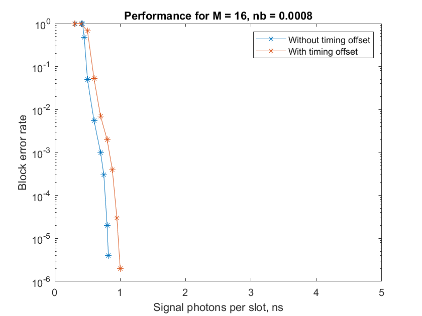
Plot Block Error Rate
figure
blockER = blockErrors./totalBlocks;
plot(ns, blockER,"*-")
xlim([ns(1) ns(end)+2])
xlabel("Signal photons per slot, ns")
ylabel("Block error rate")
title("Performance for ModOrder = "+num2str(cfgParams.ModOrder)+", nb = "+num2str(nb))

This figure compares the block error rate analysis for the Poisson channel, APD Gaussian channel, and PMT Gaussian channel in a CCSDS HPE TM optical link. The analysis is based on 1e6 frames with InfoSize = 7526, ModOrder = 16, NumRegisters = 18, RegisterLengthStep = 420, RepeatFactor = 2, TFLength = 1024 bytes, numTF = 20, nb = 0.05, and maxNumBlocks = 1000.
This table shows the managed parameters for the HPE telemetry signaling.

Appendix
The example uses these helper files:
HelperCCSDSHPETMTimingSynchronizer.m— Perform timing synchronizationHelperCCSDSHPETMSymbolSynchronizer.m— Perform symbol synchronizationHelperPMTGaussianChannel.m— Model PMT channel using Gaussian approximation
References
[1] The Consultative Committee for Space Data Systems. Optical Communications Coding and Synchronization, Recommended Standard, Issue 1. CCSDS 142.0-B-1. Washington, D.C.: CCSDS, August 2019. https://ccsds.org/index.php?gf-download=2025%2F01%2F%2F142x0b1.pdf.
[2] Moision, B., and J. Hamkins. “Coded Modulation for the Deep-Space Optical Channel: Serially Concatenated Pulse-Position Modulation.” Interplanetary Network Progress Report 42–161 (May 1, 2005): 1–25. https://ui.adsabs.harvard.edu/abs/2005IPNPR.161T...1M.
[3] Srinivasan, Meera, Ryan Rogalin, Norman Lay, Matthew Shaw, and Andre Tkacenko. “Downlink Receiver Algorithms for Deep Space Optical Communications.” edited by Hamid Hemmati and Don M. Boroson, 100960A. San Francisco, California, United States, 2017. https://doi.org/10.1117/12.2254887.
[4] Rogalin, Ryan, and Meera Srinivasan. “Maximum Likelihood Synchronization for Pulse Position Modulation with Inter-Symbol Guard Times.” In 2016 IEEE Global Communications Conference (GLOBECOM), 1–6. Washington, DC, USA: IEEE, 2016. https://doi.org/10.1109/GLOCOM.2016.7841980.
[5] K. J. Quirk, and M. Srinivasan. "Optical PPM Demodulation from Slot-Sampled Photon Counting Detectors." In MILCOM 2013 - 2013 IEEE Military Communications Conference; San Diego, California, USA, 18–20 November 2013.
[6] Connelly, J. “Repeat-PPM Super-Symbol Synchronization.” Interplanetary Network Progress Report 42–207 (November 1, 2016): 1–24. https://ui.adsabs.harvard.edu/abs/2016IPNPR.207A...1C.
[7] Schlemmer, Harald, Nemanja Stamenic, Balazs Ferenczi, and Michael Schoenhuber. “Results from a CCSDS-Compliant High Photon Efficiency Downlink SDR Platform.” In 2019 8th International Workshop on Tracking, Telemetry and Command Systems for Space Applications (TTC), 1–5. Darmstadt, Germany: IEEE, 2019. https://doi.org/10.1109/TTC.2019.8895458.
[8] Dolinar, S., D. Divsalar, D., Hamkins, J. and Pollara, F.,2000, June. “Capacity of PPM on Gaussian and WebbChannels." In 2000 IEEE International Symposium on Information Theory, IEEE, 2000.
[9] R. J. Stokey, and P. J. Lee. "Approximation to the probability density at the output of a photomultiplier tube." The Telecommunications and Data Acquisition Progress Report 42-73 (January-March 1983)