GPS L1C Waveform Generation
This example shows you how to generate Global Positioning System (GPS) civil navigation baseband waveform on L1 (1575.42 MHz) with binary offset carrier (BOC) modulation. This waveform is called as GPS L1C waveform. This waveform uses the civil navigation data on L1C (CNAV-2), as defined in IS-GPS-800 [1].
Introduction
GPS L1C is a modernized civil navigation signal transmitted on the L1 band (1575.42 MHz). GPS L1C uses the BOC modulation scheme. This modulation scheme enables efficient use of the L1 band so that the new signal does not interfere with existing legacy signals. The frame structure, data encoding technique, spreading the data with the ranging codes, and modulation technique of GPS L1C differs significantly from the legacy navigation signals defined in IS-GPS-200 [2]. This table compares various attributes of three waveforms: legacy navigation (LNAV), L2C civil navigation (CNAV), and L1C civil navigation (CNAV-2).
You can generate an L1C waveform by following these steps.
Generate data, as defined in IS-GPS-800.
Spread the data by using the ranging codes, as defined in IS-GPS-800. L1C uses two types of ranging codes: a ranging code for the data ( code) and a ranging code for the pilot ( code). The chip rate of both and codes is 1.023 mega chips per second with 10 milliseconds in length. Therefore, number of chips before repeating is 10230.
Modulate the code with the user data bits to obtain the data component. The rate of user data bits is 100 bits per second.
Modulate the code with the overlay code ( code) to obtain the pilot component. The rate of code is 100 bits per second.
Modulate the data component by using BOC (1,1).
Modulate the pilot component by using the time multiplexed BOC (TMBOC) modulation technique.
This figure shows the workflow to generate an L1C waveform.
GPS L1C Signal Structure
The data rate of CNAV-2 data is 100 bits per second. Each frame of CNAV-2 data consists of 1800 bits, which you can divide into three subframes per IS-GPS-800.
The first subframe consists of 52 bits and contains the time of interval (TOI) information. The actual length of the TOI information is 9 bits, but the Bose Choudhuri Hocquenghem (BCH) encoder encodes these 9 bits and outputs 52 bits.
The second subframe consists of 1200 bits and contains the clock and ephemeris data. The actual length of clock and ephemeris data is 600 bits, but the low-density parity-check code (LDPC) encoder encodes these 600 bits and outputs 1200 bits. The data in the second subframe remains constant over multiple frames until the GPS control segment (CS) updates it.
The third subframe consists of 548 bits and can include almanac data, Earth orientation parameters, differential correction parameters, ionosphere parameters, Universal Coordinated Time (UTC) parameters, text messages, and satellite vehicle configurations. The actual length of the information is 274 bits, but the LDPC encoder encodes these 274 bits and outputs 548 bits. The data in the third subframe changes from frame to frame. For more information about data in subframes, see IS-GPS-800 [1].
The second and third subframes together constitute 1748 bits. To get one frame of CNAV-2 data, append the 1748 interleaved bits of the second and third subframe to the first subframe. This figure, reproduced from Figure 3.2-3 of IS-GPS-800, shows the frame structure of L1C navigation data.
GPS CNAV-2 Data Initialization and Waveform Generation
In this example, you generate data for one satellite. To initialize the satellite, specify its pseudo random noise number (PRNID). Also specify the number of bits for which to generate the waveform and the chip rate of the ranging code. Because the sampling rate of the waveform is at a much higher rate, in the millions of samples per second, compared to the data, at 100 bits per second, a typical computer does not have enough memory to hold the number of samples required to generate an entire frame. Using the numBits property enables you to specify the number of data bits to generate waveform.
PRNID = 1;
numBits = 10;       % Generate waveform for 10 data bits
chipRate = 1.023e6; % Chip rate of the ranging code. This is a constant value
Set the WriteWaveformToFile property to write the baseband waveform to a file if needed.
writeWaveformToFile =  false;
Initialize the CNAV-2 data by using the HelperGPSNavigationConfig helper object. This object holds all the navigation information, including the clock, ephemeris, and almanac. For more information about these satellite orbital parameters, see the GPS Waveform Generation example.
cfgCNAV2 = HelperGPSNavigationConfig(SignalType = "CNAV2", ...
    PRNID = PRNID)
cfgCNAV2 =
  HelperGPSNavigationConfig with properties:

                           SignalType: "CNAV2"
                                PRNID: 1
             L1CSubframe3PageSequence: [49×1 double]
                               L1CTOI: 0
                              L1CITOW: 0
                            L1CHealth: 0
                           WeekNumber: 2149
               GroupDelayDifferential: 0
                  SemiMajorAxisLength: 26560000
            ChangeRateInSemiMajorAxis: 0
                 MeanMotionDifference: 0
           RateOfMeanMotionDifference: 0
                         Eccentricity: 0.0200
                          MeanAnomaly: 0
             ReferenceTimeOfEphemeris: 0
              HarmonicCorrectionTerms: [6×1 double]
                  IntegrityStatusFlag: 0
                    ArgumentOfPerigee: -0.5200
                 RateOfRightAscension: 0
             LongitudeOfAscendingNode: -0.8400
                          Inclination: 0.3000
                      InclinationRate: 0
                              URAEDID: 0
                InterSignalCorrection: [4×1 double]
                              ISCL1CP: 0
                              ISCL1CD: 0
          ReferenceTimeCEIPropagation: 0
    ReferenceWeekNumberCEIPropagation: 101
                             URANEDID: [3×1 double]
                      AlmanacFileName: "gpsAlmanac.txt"
                           Ionosphere: [1×1 struct]
                     EarthOrientation: [1×1 struct]
                                  UTC: [1×1 struct]
               DifferentialCorrection: [1×1 struct]
                           TimeOffset: [1×1 struct]
                       ReducedAlmanac: [1×1 struct]
                          TextMessage: 'This content is part of Satellite Communications Toolbox. Thank you. '
                                  ISM: [1×1 struct]
Pass the configuration object cfgCNAV2 of the HelperGPSNAVDataEncode helper function, which encodes the CNAV-2 data. The L1CSubframe3PageSequence property of cfgCNAV2 controls the page order for the third subframe and number of frames output by the data encoder.
dataCNAV2 = HelperGPSNAVDataEncode(cfgCNAV2);
Generate the ranging codes and overlay codes by using the gpsL1CCodes function.
[l1cd,l1cp,l1co] = gpsL1CCodes(PRNID); % Generate the codes for the specified PRNIDGenerate a TMBOC-modulated pilot code. This example makes these assumptions.
The data starts from the first index of a frame.
The overlay code is time-synchronized with the data.
numChipsPerCode = round(10e-3*chipRate);

% Initialize overlay code. Initialize indices to circularly start from 1
% after reading 1800 bits.
overlayCodeIndices = mod((1:numBits)-1,size(l1co,1))+1;
overlayBits = l1co(overlayCodeIndices);

% TMBOC indices initialization as given in section 3.3 of IS-GPS-800 [1]
ut = [0; 4; 6; 29];
vt = 0:309;

boc61Indices = reshape(ut + 33*vt,[],1);
boc11Indices = setdiff(0:10229,boc61Indices);
m6 = 6;
m1 = 1;
n = 1;
halfCyclSPS61 = 2;
halfCyclSPS11 = m6*halfCyclSPS61;
sps = halfCyclSPS11*2;
numChipsPerBit = 10230;
tmbocSig = zeros(numChipsPerBit*sps,numBits);
oneBitSig = zeros(sps,numChipsPerBit);
for ibit = 1:numBits
    l1cpo = xor(l1cp,overlayBits(ibit));
    oneBitSig(:,boc61Indices+1) = reshape(-1*bocmod(l1cpo(boc61Indices+1),m6,n),sps,[]);
    oneBitSig(:,boc11Indices+1) = reshape(-1*bocmod(l1cpo(boc11Indices+1),m1,n,halfCyclSPS11),sps,[]);
	tmbocSig(:,ibit) = oneBitSig(:);
end
Generate a BOC-modulated signal such that the rate of the generated signal and the TMBOC signal match.
spreadBitsData = xor(l1cd,dataCNAV2(1:numBits).');
l1cdSig = -1*bocmod(spreadBitsData(:),1,1,halfCyclSPS11); % L1CD is modulated by BOC(1,1). This is at a sampling rate of 2*HalfCycleSPS11*1.023e6
Combine the TMBOC- and BOC-modulated signals. Attenuate the power in the BOC-modulated data signal by 4.75 dB, as specified in Table 3.2-1 of IS-GPS-800 [1]. Both the data signal and pilot signal are present in the same phase as that of the P(Y)-code in IS-GPS-200. Combine both signals to obtain a real signal.
% Scale and add the signals. Both the pilot and data channels of GPS L1C
% have the phasing similar to the P(Y)-code of the legacy GPS signal.
scaleFactordB = 4.75;                        % dB Watts
scaleFactor = 10^(scaleFactordB/10);
llcdSigScaled = l1cdSig/sqrt(scaleFactor);
gpsL1CWaveform = tmbocSig(:) + llcdSigScaled;
Write waveform to file.
fs = sps*chipRate;
if writeWaveformToFile == 1
    bbWriter = comm.BasebandFileWriter("Waveform.bb",fs,0);
    bbWriter(gpsL1CWaveform)
end
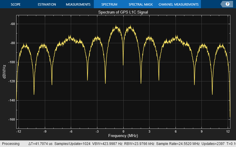
Visualize the spectrum of the generated waveform.
gpsScope = spectrumAnalyzer(SampleRate = fs, ...
    Title = "Spectrum of GPS L1C Signal", ...
    SpectrumType = "power-density", ...
    SpectrumUnits = "dBW/Hz");
gpsScope(gpsL1CWaveform/rms(gpsL1CWaveform))
Further Exploration
Multi-satellite waveform — This example shows GPS L1C waveform generation for one satellite. For an example on how to generate multi-satellite waveform from a GPS satellite scenario, see GNSS Signal Transmission Using Software-Defined Radio example.
Custom sample rate — The example assumes a fixed sample rate to generate the waveform. This code shows how to generate a waveform for a custom sample rate, using the
gpsWaveformGeneratorSystem object™.
% customSampleRate = 25e6;
% prn = [2 5 12 21];
% numbits = 10;
% numsat = length(prn);
% databits = randi([0,1],numbits,numsat);                % Generate random data bits
% waveobj = gpsWaveformGenerator(SignalType="l1c", ...
%     PRNID=prn,SampleRate=customSampleRate)
% l1cwaveform = waveobj(databits);
% size(l1cwaveform)
Design receivers — Use
gnssSignalAcquirerandgnssSignalTrackerfeatures to acquire and track GNSS waveforms at the receiver. For more information on how to perform receiver acquisition and tracking for GPS L1C signals, see GPS Receiver Acquisition and Tracking example. For GPS receiver processing steps, see GPS Legacy Navigation Receiver Positioning Using C/A-Code example.
Supporting Files
This example uses these helper and data files:
gpsAlmanac.txt— Almanac data file downloaded from Navcen websiteHelperGPSNAVDataEncode.m— Encode navigation data into bits from data in configuration objectHelperGPSNavigationConfig.m— Create configuration object for GPS navigation dataL1CLDPCParityCheckMatrices.mat— LDPC parity check matrix for encoding L1C data
Bibliography
[1] IS-GPS-800, Rev: J. NAVSTAR GPS Space Segment/User segment L1C Interfaces. Aug 22, 2022; Code Ident: 66RP1.
[2] IS-GPS-200, Rev: N. NAVSTAR GPS Space Segment/Navigation User Segment Interfaces. Aug 22, 2022; Code Ident: 66RP1.