Model Clutches with Viscous Friction Loss
A source of loss in a clutch system coupling two driveshafts comes from viscous friction at the two shaft bearings. Consider the Custom Clutch example model. Here you add a kinetic friction torque proportional to the angular velocity on both sides of the clutch (viscous friction). The Simscape™ Foundation library provides a Rotational Damper block that represents such a damper. The angular motion of the driveshafts is relative to another component. Here the angular velocities of the shafts are measured relative to rotational ground, represented by Mechanical Rotational Reference. You can make a friction subsystem that applies such a torque to any driveline axis connected to it. You can copy the subsystem and modify the existing clutch model by connecting the two copies on either side of the clutch.
Note
The velocity used in this damping is the absolute velocity of a single shaft relative to rest. If you had two rotating driveline shafts and wanted to exert a relative damping between them as a function of their relative velocities, use the same Rotational Damper block connected between the two axes.
Creating a Torque Damping Subsystem
The viscous friction torque is τfric = –μω, where μ is the viscous friction coefficient. To implement this torque:
To open the model from the Engage and Disengage Gears Using a Clutch example, enter
openExample('sdl/CustomClutchExample')From the Simscape library, copy Mechanical Rotational Reference, Rotational Damper, and Connection Port into your model window.
From the Simscape Driveline™ Couplings & Drives > Springs & Dampers library, copy the Rotational Damper block into your model window.
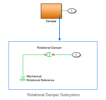
Connect the Mechanical Rotational Reference to the case (C) port of the Rotational Damper and the rod (R) port of the Rotational Damper to the Connection Port.
For the Rotational Damper block, for the Damping coefficient, enter
0.3. Leave the default units.Select the whole connected three-block set, and create a subsystem. Name the subsystem
Damper 1.Create a second copy of
Damper. Name the new subsystemDamper 2.
Rotational Damping Subsystem

Connecting and Simulating the Damped Clutch System
Complete and run the model.
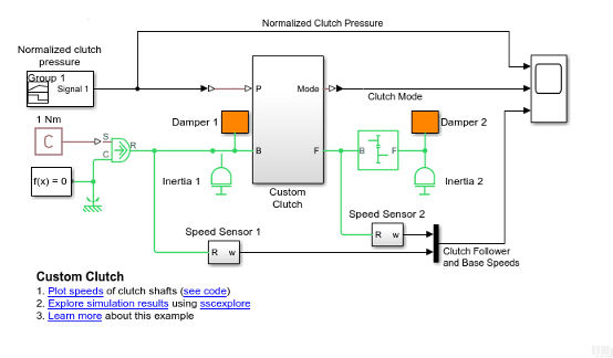
Connect the two Damper subsystems to the driveline of the clutch model, as shown in the figure.
Damped Custom Clutch Model

Change the simulation time to 20 seconds.
Open the Scope blocks and click Start. To see the full plots, readjust the horizontal axes of the Scope using Autoscale.

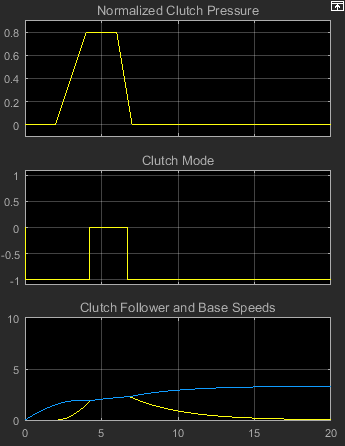
The clutch pressure and external torques are applied as before. The shafts now rotate slower because of the damping.
As before, Inertia2 begins to spin when the clutch starts to engage at 2 seconds. After the clutch locks at 4 seconds, the body continues to accelerate, at a slower rate than it did without damping. At about 6.7 seconds, the clutch begins to disengage and completely disengages at 7 seconds. Subject to friction, Inertia2 now starts to slow down, unlike in the friction-free case. Once the external torque is removed, its angular velocity drops exponentially with time.
The behavior of Inertia1 is more complex. It begins to spin up, at a lower rate than before, because of the damping. From 2–7 seconds in the simulation, Inertia1 shares the external torque with Inertia2 via the Clutch and the Simple Gear. After 7 seconds, the external torque applies to Inertia1 alone. It continues to accelerate, at an ever-slowing rate, because of the damping. If you let the simulation run without stopping, Inertia approaches its terminal angular velocity, a state where the frictional torque exactly balances the externally applied torque. This terminal velocity is ωterm = τext/μ or 1/0.3 = 3.3333 radians/second. The third Scope plot approaches this terminal value.