Prototype a Component and Get Instant Feedback
This example shows how you can interactively modify the component source and get instant feedback on the resulting block implementation.
If
you make a mistake (for example, omit the end keyword) when editing
the component source, then when you refresh the block, the compiler issues a diagnostic
error message, pointing to the appropriate line in the code.
Open the Simscape > Foundation Library > Electrical > Electrical Elements > Variable Resistor block dialog box. On the Description tab, click the Source code link. The underlying source code opens in the Editor window.
component variable_resistor
% Variable Resistor :1.5
% Models a linear variable resistor. The relationship between voltage V
% and current I is V=I*R where R is the numerical value presented at the
% physical signal port R. The Minimum resistance parameter prevents
% negative resistance values.
%
% Connections + and - are conserving electrical ports corresponding to
% the positive and negative terminals of the resistor respectively. The
% current is positive if it flows from positive to negative, and the
% voltage across the resistor is given by V(+)-V(-).

% Copyright 2005-2023 The MathWorks, Inc.

inputs
    R = { 0.0, 'Ohm' }; % R:left
end

nodes
    p = foundation.electrical.electrical; % +:left
    n = foundation.electrical.electrical; % -:right
end

nodes(ExternalAccess=none)
    H = foundation.thermal.thermal; % H:top
end

parameters
    Rmin = { 0, 'Ohm' }; % Minimum resistance R>=0
    thermalEnable = false; % Add thermal port
end

parameters(ExternalAccess=none)
    thermal_mass = {1, 'J/K'}; % Thermal mass
end

variables
    i = { 0, 'A' }; % Current
    v = { 0, 'V' }; % Voltage
end

variables(ExternalAccess=none)
    T = {300, 'K'}; % Temperature
end

branches
    i : p.i -> n.i;
end

intermediates
    power_dissipated = v*i; % Dissipated power
end

equations
    H.T == T;
    assert(Rmin>=0)
    v == p.v - n.v;
    if R > Rmin
        v == i*R;
    else
        v == i*Rmin;
    end
end

annotations
    H: Side = top;
end

if thermalEnable
    annotations
        [H, T, thermal_mass] : ExternalAccess=modify;
        Icon = 'variable_resistor_thermal.svg';
    end
    variables
        Q = { 0, 'W' }; % Heat flow into junction
    end
    branches
        Q : H.Q -> *;
    end

    equations
        assert(thermal_mass>=0);
    end

    if thermal_mass == 0
        equations
            Q + power_dissipated == 0;
        end
    else
        equations
            assert(isfinite(thermal_mass));
            Q + power_dissipated == thermal_mass * der(H.T);
        end
    end
else
    annotations
        [H, T, thermal_mass] : ExternalAccess=none;
    end
    connections
        connect(H,*)
    end
end

end
Change the component name in the first line:
component my_var_resSave the source code as a file called
my_var_res.sscin your current working folder.To create a new model with optimal settings for physical modeling, in the MATLAB® Command Window, type:
sscnew
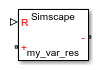
Open the Simscape > Utilities library and add the Simscape Component block to your model. At first, the block does not point to any component file, therefore it does not have any ports and the block icon says
Unspecified.
Double-click the block to open the source file selector dialog box. Select the
my_var_res.sscfile.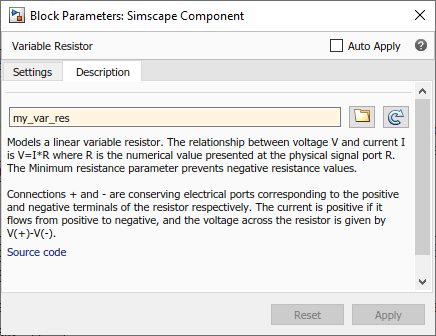
Close the block dialog box. The block icon gets updated, reflecting the selected source component. It now has two conserving electrical ports, + and -, and a physical signal input port R.
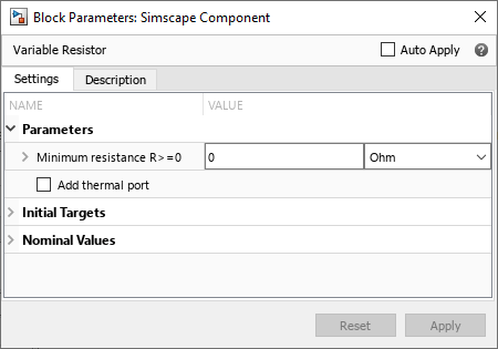
Double-click the block to open its dialog box. At this point, it has the same block name, description, parameters, and variables, as the Variable Resistor block in the Foundation library.
On the Description tab, click the Source code link to start editing the source code. Change the block name and description:
component my_var_res
% Variable Resistor with Energy Sensor
% Variable linear resistor that outputs total electrical energy.
To have the block reflect the changes to the underlying source, on the Description tab, click
 . The block dialog box updates
accordingly.
. The block dialog box updates
accordingly.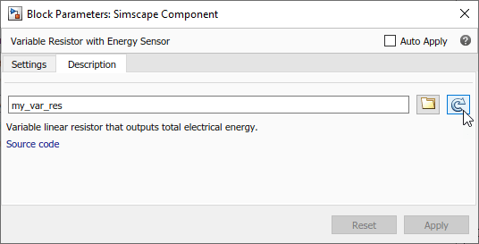
Declare the output
eand add the equation calculating total electrical energy. The component source now looks like this:component my_var_res % Variable Resistor with Energy Sensor % Variable linear resistor that outputs total electrical energy. inputs R = { 0.0, 'Ohm' }; % R:left end outputs e = { 0, 'J' }; end nodes p = foundation.electrical.electrical; % +:left n = foundation.electrical.electrical; % -:right end nodes(ExternalAccess=none) H = foundation.thermal.thermal; % H:top end parameters Rmin = { 0, 'Ohm' }; % Minimum resistance R>=0 thermalEnable = false; % Add thermal port end parameters(ExternalAccess=none) thermal_mass = {1, 'J/K'}; % Thermal mass end variables i = { 0, 'A' }; % Current v = { 0, 'V' }; % Voltage end variables(ExternalAccess=none) T = {300, 'K'}; % Temperature end branches i : p.i -> n.i; end intermediates power_dissipated = v*i; % Dissipated power end equations H.T == T; assert(Rmin>=0) v == p.v - n.v; if R > Rmin v == i*R; else v == i*Rmin; end e == integ(v*i); end annotations H: Side = top; end if thermalEnable annotations [H, T, thermal_mass] : ExternalAccess=modify; Icon = 'variable_resistor_thermal.svg'; end variables Q = { 0, 'W' }; % Heat flow into junction end branches Q : H.Q -> *; end equations assert(thermal_mass>=0); end if thermal_mass == 0 equations Q + power_dissipated == 0; end else equations assert(isfinite(thermal_mass)); Q + power_dissipated == thermal_mass * der(H.T); end end else annotations [H, T, thermal_mass] : ExternalAccess=none; end connections connect(H,*) end end endRefresh the block again. The block icon now has an additional physical signal output port e.

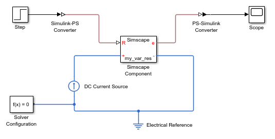
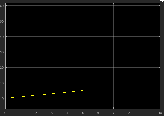
Connect the block to a simple test rig to verify the correct performance.
Note
There is a limitation that the name of the model cannot be the same as the name of the source file for the Simscape Component block. Therefore, if you save the test rig model, make sure to give it a different name, such as
my_var_res_test.