Increment Stored Integer
R2026bIncrease stored integer value of signal by one
Increment Stored Integer block
To add a block to a model, double-click the canvas and start typing the block name. Then, select the block from the list.
Libraries:
Simulink /
Additional Math & Discrete /
Additional Math: Increment - Decrement
HDL Coder /
Math Operations
Description
The Increment Stored Integer block increases the stored integer value of a signal by one.
Floating-point signals also increase by one, and overflows always wrap.
Examples
This example shows how to increase and decrease the stored integer value of a signal by one.
The Increment Stored Integer block increases the stored integer value of the input signal by one.
The Decrement Stored Integer block decreases the stored integer value of the input signal by one.
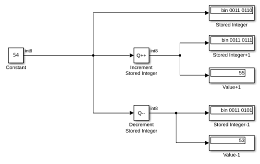
If you change the value of the input signal to 127 (the maximum value representable by an int8 data type), incrementing the stored integer value by one causes an overflow. Because overflows in the Increment and Decrement Stored Integer blocks always wrap, the Increment Stored Integer block will output a value of -128.
Ports
Input
Input signal, specified as a scalar, vector, or matrix.
Data Types: single | double | int8 | int16 | int32 | int64 | uint8 | uint16 | uint32 | uint64 | fixed point
Output
Output is the stored integer value of the input signal increased by one. Floating-point signals also increase by one, and overflows always wrap. The output has the same data type and dimensions as the input.
Data Types: single | double | int8 | int16 | int32 | int64 | uint8 | uint16 | uint32 | uint64 | fixed point
Block Characteristics
Data Types |
|
Direct Feedthrough |
|
Multidimensional Signals |
|
Variable-Size Signals |
|
Zero-Crossing Detection |
|
Extended Capabilities
The code generator does not explicitly group primitive blocks that constitute a nonatomic masked subsystem block in the generated code. This flexibility allows for more efficient code generation. In certain cases, you can achieve grouping by configuring the masked subsystem block to execute as an atomic unit by selecting the Treat as atomic unit option.
HDL Coder™ provides additional configuration options that affect HDL implementation and synthesized logic.
This block has one default HDL architecture.
General
| HDL Property | Description |
|---|---|
| ConstrainedOutputPipeline | Number of registers to place at
the outputs by moving existing delays in the design. Distributed pipelining
does not redistribute these registers. The default value is
|
| InputPipeline | Number of input pipeline stages
to insert in the generated code. Distributed pipelining and constrained
output pipelining can move these registers. The default value is
|
| OutputPipeline | Number of output pipeline stages
to insert in the generated code. Distributed pipelining and constrained
output pipelining can move these registers. The default value is
|
| SynthesisAttributes |
Specifies the synthesis attributes for the blocks and block output signals in the model. The generated HDL code contains these attributes. For more information, see SynthesisAttributes (HDL Coder). |
This table lists the data types that the input port supports for HDL code generation:
| Input Port | Dimensions | Fixed-Point Values | Floating-Point Values | Built-in Integers | Bus Signals | Boolean Values | Complex Values |
|---|---|---|---|---|---|---|---|
| Port_1 | Scalar Vector Matrices up to two dimensions | Yes | Half Single Double | Yes | No | No | No |
To generate HDL code using native floating-point input data types, open the HDL Code Generation > Floating-Point pane in the Configuration Parameters dialog box and select the Use floating-point parameter. For more information, see Generate Target-Independent HDL Code with Native Floating-Point (HDL Coder).
When you use half, single, or
double data types as inputs to the block, you can use the
Latency Strategy (HDL Coder) model configuration parameter to
specify whether the blocks latency maps to minimum or maximum latency values
when using native floating-point libraries. The block supports these native
floating-point latency values:
| Floating-Point Data Type | Latency Strategy Setting | Latency Cycles | Custom Latency Support |
|---|---|---|---|
double | MIN | 6 | No |
MAX | 11 | ||
single | MIN | 6 | No |
MAX | 11 | ||
half | MIN | 4 | No |
MAX | 8 |
The block uses multicycle implementations to introduce additional latency in the generated code. To see the added latency, view the generated model or validation model. See Generated Model and Validation Model (HDL Coder).
You can use these HDL Coder optimizations to optimize the speed, area, and I/Os.
Area Optimization
| Optimization | Description |
|---|---|
| Resource Sharing (HDL Coder) | Resource sharing is an area optimization in which HDL Coder identifies multiple functionally equivalent resources and replaces them with a single resource. |
| Streaming (HDL Coder) | Streaming is an area optimization in which HDL Coder transforms a vector data path to a scalar data path or to several smaller-sized vector data paths. |
Speed Optimization
| Optimization | Description |
|---|---|
| Specify Distributed Pipelining Settings (HDL Coder) | Distributed pipelining, or register retiming, is a speed optimization that moves existing delays in a design to reduce the critical path while preserving functional behavior. |
| Clock-Rate Pipelining (HDL Coder) | Clock-rate pipelining is an optimization framework that allows other speed and area optimizations to introduce latency at the clock rate. |
| Specify Adaptive Pipelining Settings (HDL Coder) | Adaptive pipelining optimization creates patterns or combination of blocks with registers that can improve the achievable clock frequency and reduce the area usage on the FPGA boards by inserting pipeline registers to the blocks in your design. |
| Critical Path Estimation (HDL Coder) | To quickly identify the most likely critical path in your design, use critical path estimation. Critical path estimation speeds up the iterative process of finding the critical path. To know blocks that are characterized in critical path estimation, see Characterized Blocks (HDL Coder). |
Fixed-Point Conversion
Design and simulate fixed-point systems using Fixed-Point Designer™.
Version History
Introduced before R2006aYou can now generate synthesizable HDL code for the Increment Stored
Integer block when using native floating-point data types, including
half, single, or
double.
You can also use various HDL optimizations, such as distributed pipelining, hierarchy flattening, or delay balancing to generate optimized HDL code for the block.
Use the SynthesisAttributes HDL block property to specify the synthesis attributes for the block and its output signals. HDL Coder includes these attributes in the generated HDL code.
MATLAB Command
You clicked a link that corresponds to this MATLAB command:
Run the command by entering it in the MATLAB Command Window. Web browsers do not support MATLAB commands.
Sélectionner un site web
Choisissez un site web pour accéder au contenu traduit dans votre langue (lorsqu'il est disponible) et voir les événements et les offres locales. D’après votre position, nous vous recommandons de sélectionner la région suivante : .
Vous pouvez également sélectionner un site web dans la liste suivante :
Comment optimiser les performances du site
Pour optimiser les performances du site, sélectionnez la région Chine (en chinois ou en anglais). Les sites de MathWorks pour les autres pays ne sont pas optimisés pour les visites provenant de votre région.
Amériques
- América Latina (Español)
- Canada (English)
- United States (English)
Europe
- Belgium (English)
- Denmark (English)
- Deutschland (Deutsch)
- España (Español)
- Finland (English)
- France (Français)
- Ireland (English)
- Italia (Italiano)
- Luxembourg (English)
- Netherlands (English)
- Norway (English)
- Österreich (Deutsch)
- Portugal (English)
- Sweden (English)
- Switzerland
- United Kingdom (English)