Analog Input
R2026bRead ADC register value after ADC conversion at analog pin of Arduino AVR core
Since R2024a
Analog Input Advanced AVR block
To add a block to a model, double-click the canvas and start typing the block name. Then, select the block from the list.
Libraries:
Simulink Support Package for Arduino Hardware /
Advanced /
AVR
Description
Add-On Required: This feature requires the Simulink Support Package for Arduino Hardware add-on.
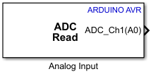
Use the Analog Input block to read the value from an ADC register after analog to digital conversion on the Arduino® AVR analog pin. You can use the block to read up to three analog voltage outputs simultaneously.
Note
The Analog Input block supports C/C++ code generation. This feature allows you to generate C and C++ code using Embedded Coder®.
Ports
Output
The block outputs the digitally converted voltage data received by the analog
input pin of the Arduino board. The number of output ports depends on the number of analog input
pins you specify in the Number of analog input pins parameter.
For example, if you set the Number of analog input pins parameter
to 3, the block enables three output ports with port names
ADC_Ch1(A0), ADC_Ch2(A1), and
ADC_Ch3(A2).
Data Types: double
Parameters
Select the number of inputs for analog to digital conversion.
Enter the Arduino board analog input pin number. To open the Arduino pin mapping table, click View pin map. For more information on how to assign pins for the Analog Input block, see Pin Mapping for Arduino Timer-Independent Blocks.
The number of Pin Number parameters depends on the number of
analog input pins you specify in the Number of analog input pins
parameter. For example, if you set the Number of analog input pins
parameter to 3, the block enables the Pin number
2 and Pin number 3 parameters. You can enter the
analog pin numbers for the Arduino board accordingly.
Select a timer/counter trigger to start the ADC conversion on the positive edge of the trigger. Connect the Arduino hardware board pin to the PWM input signal using the PWM block to enable the timer/counter.
Free running mode— Operates independently of the clock and triggers an ADC conversion by the end of the previous conversion.Timer/Counter 0 Compare Match A— Trigger an ADC conversion once the value of the Timer/Counter 0 matches the value stored in the output compare register (OCR) A.Timer/Counter 0 Overflow— Triggers an ADC conversion when the value set in the Timer/Counter 0 register reaches its maximum value.Timer/Counter 1 Compare Match B— Trigger an ADC conversion once the value of the Timer/Counter 0 matches the value stored in OCR B.Timer/Counter 1 Overflow— Triggers an ADC conversion when the value set in the Timer/Counter 1 register reaches its maximum value.Timer/Counter 4 Overflow— Triggers an ADC conversion when the value set in the Timer/Counter 4 register reaches its maximum value.Timer/Counter 4 Compare Match A— Trigger an ADC conversion once the value of the Timer/Counter 4 matches the value stored in OCR A.Timer/Counter 4 Compare Match B— Trigger an ADC conversion once the value of the Timer/Counter 4 matches the value stored in OCR B.Timer/Counter 4 Compare Match D— Trigger an ADC conversion once the value of the Timer/Counter 4 matches the value stored in OCR D.
For more information about supported ADC trigger sources and board-specific constraints, see Supported ADC Trigger Sources for Arduino AVR Boards.
Select this option to generate an interrupt after the analog voltage at the pin of the Arduino hardware is converted to its equivalent digital voltage.
Note
Once you enable this parameter, make sure to select the appropriate Interrupt group and Interrupt name parameters in the Hardware Interrupt for AVR block.
More About
The availability of ADC trigger sources depends on the AVR microcontroller used on the selected board. This table lists the supported ADC trigger sources across the supported Arduino AVR boards.
| ADC Trigger Source | ATMega2560 (Arduino Mega 2560 / Mega ADK) | ATMega328P (Arduino Uno / Nano) | ATMega32u4 (Arduino Leonardo / Micro / Robot Motor / Robot Control) |
|---|---|---|---|
| Free running mode | ✔ | ✔ | ✔ |
| Timer/Counter 0 Compare Match A | ✔ | ✔ | ✔ |
| Timer/Counter 0 Overflow | ✔ | ✔ | ✔ |
| Timer/Counter 1 Compare Match B | ✔ | ✔ | ✔ |
| Timer/Counter 1 Overflow | ✔ | ✔ | ✔ |
| Timer/Counter 4 Overflow | ❌ | ❌ | ✔ |
| Timer/Counter 4 Compare Match A | ❌ | ❌ | ✔ |
| Timer/Counter 4 Compare Match B | ❌ | ❌ | ✔ |
| Timer/Counter 4 Compare Match D | ❌ | ❌ | ✔ |
Version History
Introduced in R2024a
See Also
MATLAB Command
You clicked a link that corresponds to this MATLAB command:
Run the command by entering it in the MATLAB Command Window. Web browsers do not support MATLAB commands.
Sélectionner un site web
Choisissez un site web pour accéder au contenu traduit dans votre langue (lorsqu'il est disponible) et voir les événements et les offres locales. D’après votre position, nous vous recommandons de sélectionner la région suivante : .
Vous pouvez également sélectionner un site web dans la liste suivante :
Comment optimiser les performances du site
Pour optimiser les performances du site, sélectionnez la région Chine (en chinois ou en anglais). Les sites de MathWorks pour les autres pays ne sont pas optimisés pour les visites provenant de votre région.
Amériques
- América Latina (Español)
- Canada (English)
- United States (English)
Europe
- Belgium (English)
- Denmark (English)
- Deutschland (Deutsch)
- España (Español)
- Finland (English)
- France (Français)
- Ireland (English)
- Italia (Italiano)
- Luxembourg (English)
- Netherlands (English)
- Norway (English)
- Österreich (Deutsch)
- Portugal (English)
- Sweden (English)
- Switzerland
- United Kingdom (English)